
How to Choose Acetate Cloth Tape Width for Coil Wrapping
Technical Insights · Coil Wrapping Process Design
Choose a width that wraps cleanly.
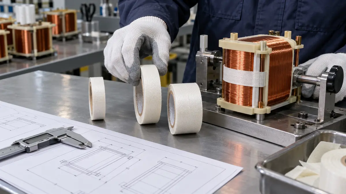
Choosing acetate cloth tape width for coil wrapping is a geometry and process decision, not a request for the widest roll that fits. The correct width must cover the released insulation zone while following bobbin shoulders, corners, leads, terminals, and winding contours without wrinkles, excessive tension, loose edges, or unnecessary material buildup.
Quick Answer
Use the narrowest practical width that achieves the required coverage and overlap with acceptable cycle time and consistent placement. A very wide strip may reduce the number of turns but resist corners, bridge gaps, trap wrinkles, or interfere with leads. A very narrow strip may conform well but increase turn count, labor, cumulative overlap, and opportunity for gaps.
This guide is for transformer, motor, solenoid, and coil process engineers choosing slit widths for a documented wrapping method. It provides a coverage calculation, a comparison worksheet, and a defect-to-retest plan that can be used on non-energized sample coils. Technical content reviewed: .
Measure the Inputs Before Selecting Width
Build a width study around representative wound parts, including maximum and minimum winding height, shifted layers, lead dress, bobbin variation, and any varnish or impregnation state that changes the surface. Define whether the tape forms a band, an axial wrap, a spiral wrap, a crossover, an outer finish, or a local retention strip.
| Input | What to record | Width implication |
|---|---|---|
| Coverage zone | Start, stop, overlap, edge margin, and terminal keep-out | Defines the usable coverage per turn |
| Coil envelope | Width, height, corner radius, steps, and surface variation | Sets conformity demand and bridging risk |
| Lead geometry | Exit position, bend, sleeving, strain relief, and movement | May require a narrower local strip or shaped piece |
| Process method | Manual, semi-automatic, spiral, band, or indexed placement | Changes pitch accuracy and handling limits |
| Downstream exposure | Varnish, bake, assembly compression, vibration, and inspection | Determines whether edges and overlaps remain acceptable |
Understand the Width Tradeoffs
Coverage efficiency
Wider tape can cover more area per turn and reduce seams. That benefit is real only when the strip can follow the surface without folding, bridging, or lifting. Cycle time should be measured with trained operators rather than estimated from roll width.
Corner conformity
As width increases, the cloth must accommodate more difference between the inner and outer path around a corner. A narrow strip often follows compound geometry more easily. The best result may use one width for the main band and a separate small piece for a lead exit or shoulder.
Build and overlap
Every overlap adds local thickness. Narrow tape with excessive overlap can create a ridge, while wide tape may require a large pleat. Specify an overlap range and check the completed part against the space available in the housing, clamp, core, or neighboring winding.
Compare Wrapping Methods
| Method | Width preference | Main control point |
|---|---|---|
| Single band | Width close to the released band zone | Edge margin, end overlap, and straightness |
| Spiral wrap | Narrow enough to follow the coil and maintain pitch | Overlap percentage, tension, pitch, and reversal |
| Outer finish wrap | Wide enough for efficient coverage without corner pleats | Appearance, edge lift, lead access, and final build |
| Lead-exit reinforcement | Often narrower or die cut for local placement | Lead bend radius and strain-relief boundary |
| Automated banding | Matched to guide, sensor, mandrel, and programmed path | Slit tolerance, roll tracking, unwind, and cut consistency |
The material specification and wrapping method should be released together. Changing tape width without updating pitch, overlap, tension, or programmed motion can create a different insulation stack even when the product code is unchanged.
Calculate Coverage Before Ordering Trial Widths
For a simple straight axial coverage study, measure the tape's effective axial coverage b on the wrapped part and the axial advance per complete turn p. The local overlap is b − p and its fraction of effective coverage is (b − p) / b. Do not substitute roll width for b on a steep helix or compound corner; the width projected along the coil axis can differ from the slit width.
If the first turn covers b and each following turn adds p, a simple estimate for a required zone length L is N = 1 + ceil((L − b) / p) when L is greater than b; otherwise one turn is sufficient for this geometric model. “ceil” means round up to the next whole number. This estimates coverage turns only; it excludes start/finish retention, end overlap, lead-exit pieces, and the electrical insulation system's layer requirements.
| Measured effective width b | Trial pitch p | Overlap | Estimated coverage turns N | Total geometric span |
|---|---|---|---|---|
| 8.0 mm | 6.0 mm | 2.0 mm / 25% | 7 | 44.0 mm |
| 12.0 mm | 8.0 mm | 4.0 mm / 33.3% | 5 | 44.0 mm |
| 16.0 mm | 12.0 mm | 4.0 mm / 25% | 3 | 40.0 mm |
In the middle example, 12.0 + (5 − 1) × 8.0 = 44.0 mm, so the start position and excess coverage must still respect terminal keep-outs. If that candidate's measured b can fall to 11.5 mm while p rises to 8.5 mm, minimum local overlap falls to 3.0 mm. Compare that worst-case result with the drawing's required minimum before the trial. A nominally faster 16.0 mm candidate has no value if it bridges the actual bobbin shoulder.
Use a Width Trial Decision Sheet
For each candidate record actual slit width and tolerance | effective b | minimum and maximum pitch | overlap range | tension setting and method | coil geometry lot | wrap time | rework time | corner defects | maximum finished build | result after varnish/bake. Reject any candidate that fails a required coverage, access, or functional criterion before comparing labor or material use. Among the remaining candidates, compare total accepted-part time, including inspection and rework, rather than turn count alone.
Run a Controlled Width Trial
- Define acceptance. Mark required coverage, keep-outs, edge margins, build limit, and visual defects.
- Select candidate widths. Choose a narrow, target, and wider option within equipment and supplier capability.
- Measure incoming rolls. Record width tolerance, edge quality, telescoping, splice status, and unwind condition.
- Use representative coils. Include geometry extremes, lead positions, and winding variation.
- Set tension and pitch. Do not let each operator improvise application variables.
- Record cycle time. Separate actual wrapping time from setup, inspection, and rework.
- Inspect immediately. Check gaps, pleats, wrinkles, lifted edges, end position, and build.
- Run downstream processes. Include varnish, bake, cooling, assembly, and handling when applicable.
- Reinspect and test. Look for migration, edge lift, hard spots, trapped varnish, and functional effects.
- Release the full method. Document width, tolerance, overlap, tension, path, tools, and acceptance images.
Validate More Than Appearance
A smooth sample coil is not enough. The width must remain practical on real variation and must not alter the electrical, mechanical, thermal, impregnation, or assembly design. Use the product owner’s required tests and avoid claiming an insulation class or dielectric rating from a generic material description.
| Validation group | Observe | Release evidence |
|---|---|---|
| Geometry | Coverage, overlap, wrinkles, gap, lead access, and finished build | Drawing, gauge, or approved visual standard |
| Process | Cycle time, tension, pitch, roll tracking, operator variation, and rework | Production-equivalent trial record |
| Downstream | Varnish wetting, bake response, cooling, edge lift, and assembly fit | Released process window |
| Material | Slit edge, fray, adhesive transfer, storage, and lot consistency | Incoming criteria and supplier agreement |
| Functional | Electrical, thermal, vibration, and durability checks as required | Product engineering acceptance plan |
Coil-Wrapping Acceptance Record Template
Copy one record per candidate: coil drawing and revision | tape code / lot / measured width | operator and equipment | effective coverage and pitch range in mm | overlap minimum in mm | largest build in mm | defect count and sample count | wrap / inspect / rework time in seconds | varnish and bake process revision | functional-test plan and result | acceptance limit | decision / reviewer / date. Preserve before-and-after photographs of the same shoulder and lead-exit positions. An untested downstream step remains “not tested,” not “pass.”
Material compatibility is a separate release decision. UL Solutions describes an electrical insulation system as a defined combination of compatible materials, including systems used in transformers and solenoids. A tape product's individual rating or a successful width trial therefore does not establish the coil's insulation-system classification.
Troubleshoot Width-Related Defects
| Symptom | Check first | Change one variable | Retest before release |
|---|---|---|---|
| Pleat at every bobbin shoulder | Effective width versus corner geometry; tape path and tension | Trial a narrower strip or a drawing-defined local piece with other settings recorded | Shoulder contact, minimum coverage, finished build, and complete wrap time |
| Intermittent gap between spiral turns | Minimum measured b and maximum p; coil slip or guide movement | Correct the guide or reduce pitch within the approved process study | Worst-case overlap over the full coverage zone and geometry range |
| Assembly no longer fits its core or housing | Stack at overlaps, end seams, and reinforcement intersections | Revise the overlap path or seam position through drawing control | Maximum finished build, fit gauge, and required insulation coverage |
| Edges lift only after varnish or bake | Exact adhesive, storage history, surface condition, varnish chemistry, and exposure record | Hold width constant while investigating material/process compatibility | Actual downstream sequence and required insulation-system tests |
| Frayed edge or adhesive deposits at the guide | Incoming slit edge, guide wear, unwind behavior, and lot history | Contain the affected roll; correct slitting or guide condition | Incoming edge standard, roll tracking, particle condition, and wrapped-coil inspection |
If a narrower tape improves conformity but increases cycle time, compare a guided application, a different starting point, or a qualified two-width method. Record the selected width with its pitch, overlap, and tension controls so a later purchasing substitution cannot silently change the process.
Related Products and Articles
For sample sourcing, review the JTT-18RF acetate cloth adhesive tape product page and request the current construction, available slit-width tolerances, and relevant material evidence. A listed model is a candidate for evaluation, not automatic approval for the coil or insulation system.
Technical Sources and Scope
3M Acetate Cloth Electrical Tape 11 identifies coil wrapping, a conformable acetate backing, and varnish/resin absorption for that specific construction. It supports screening cloth tape for conformity and downstream resin interaction, but does not establish equivalent properties for another tape. The UL Solutions reference above supports system-level compatibility qualification. The width calculations and trial sheets are original illustrative tools, not reported factory test results.
Frequently Asked Questions
Is wider acetate cloth tape always faster for coil wrapping?
No. It may reduce turn count, but wrinkles, alignment difficulty, poor corner conformity, or rework can erase the cycle-time benefit.
How much overlap should a spiral wrap use?
The product owner should release a range based on the insulation design, tape width, pitch capability, finished build, and validation results; there is no universal percentage.
Can nominal bobbin width determine the tape width?
Not by itself. Measure the finished winding envelope, shoulders, lead exits, corners, and the actual tape path on representative parts.
When should a second tape width be used?
A narrower local strip can help at a lead exit or tight shoulder while a wider strip covers the main band, provided the combined stack and process are qualified.
What should a width-selection RFQ include?
Provide coil drawings, coverage boundary, finished geometry range, lead locations, wrap method, overlap, tension, varnish or bake exposure, volume, and acceptance criteria.
Plan an Acetate Cloth Tape Width Trial
Share the coil and bobbin drawings, winding-envelope limits, lead exits, required coverage, wrap path, current width and defects, tension method, varnish or bake cycle, equipment, annual volume, and acceptance plan. JIAO TAO TAO can prepare slit-width samples for controlled evaluation.
How to Prevent Wrinkles in PTFE Heat-Sealing Tape
How to Replace PTFE Tape on an Impulse Sealer
Related Article

Need help choosing the right industrial tape?
Send us your application details, including temperature, surface material, size, quantity and current problem. Our team will help recommend a suitable tape material or custom die-cut solution.

simon@jiaotaotao.com


+86-136 1277 5969


+86-136 1277 5969
