
How to Replace PTFE Tape on an Impulse Sealer
Technical Insights · Packaging Equipment Maintenance
How to Replace PTFE Tape on an Impulse Sealer
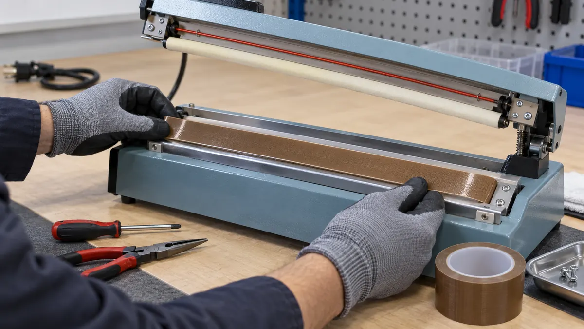
To replace PTFE tape on an impulse sealer, isolate and cool the machine, document the original strip arrangement, inspect the heater and pressure stack, clean the approved rail without damage, and install the specified PTFE construction flat and centered. The job is complete only after guards are restored and trial packages pass the released seal checks.
Quick Answer
Begin with the impulse sealer manual and original parts arrangement. Some machines use adhesive-backed PTFE tape over a stationary heater or support rail; others use a mechanically retained cover, a sleeve, a separate pad cover, or a machine-specific assembly. Match the approved replacement format. Never use tape to hide a broken heating element, damaged electrical insulation, distorted rail, worn pressure pad, loose terminal, failed sensor, or missing guard.
Identify the Exact Tape Location
An impulse sealer creates heat for a controlled time while the sealing faces clamp the package material. The functional stack may include a heating element, electrical insulation, a PTFE release cover, a resilient pressure pad, and a separate pad cover. These components have different roles and are not interchangeable.
Before removing anything, photograph or document the strip width, length, centering, folds, terminal clearances, end reliefs, overlap or butt joint, and which side of the jaw receives the cover. If the old installation differs from the manual, stop and resolve the configuration rather than copying an unapproved repair.
| Machine area | Possible PTFE role | Do not overlook |
|---|---|---|
| Stationary heater rail | Low-stick cover over the approved heating assembly | Element path, insulation, terminals, and centering |
| Opposing pressure pad | Protective cover only when specified | Compression, pad condition, and seal pressure |
| Jaw edge or guide | Release surface at an approved film-contact point | Leading-edge direction and film tracking |
| Moving hinge or arm | No general tape role unless the design specifies one | Clearance, guarding, wiring, and repeated motion |
| Damaged element or insulation | Not a repair surface | Replace with the correct service part |
Select the Correct PTFE Construction
PTFE film tape
Skived or extruded PTFE film tape can provide a smooth, thin release face on supported locations. Screen it for puncture resistance, edge curling, adhesive support, and the thickness allowed by the machine. A smooth surface is useful only if it remains flat and does not expose adhesive or heater edges.
PTFE-coated fiberglass tape
A fiberglass-reinforced construction adds dimensional support and handling strength. The weave, coating finish, stiffness, and total thickness can influence seal appearance and jaw pressure. Do not assume reinforced tape is automatically better; compare the actual strip in the intended sealer.
Machine-specific covers and zone tape
Some designs use adhesive-free zones, folded covers, prepunched reliefs, or retained sleeves. Replacing those with ordinary fully adhesive tape can change heat transfer, flex, terminal clearance, and serviceability. Purchase by the released part description or controlled drawing, not by color.
| Selection input | What to record | Why it matters |
|---|---|---|
| Sealer configuration | Model, jaw drawing, tape location, and original arrangement | Defines the permitted replacement format |
| Package material | Film structure, thickness range, coating, and contamination | Changes release and seal behavior |
| Process | Seal setting, measured heat response, pressure, cooling, and rate | Represents real cycling |
| Tape | Backing, coating, adhesive, width, thickness, liner, and lot | Controls fit and traceability |
| Acceptance | Seal appearance, strength, leak or integrity checks as applicable | Links maintenance to package quality |
Step-by-Step Replacement Workflow
- Review the service instruction. Confirm the permitted PTFE strip, tools, cleaning method, and inspection authority.
- Isolate and cool the sealer. Disconnect power, secure the arm, and verify a safe state.
- Document the existing stack. Record strip position, joints, element path, terminals, and pad arrangement.
- Remove the worn cover. Peel by the approved method without pulling, nicking, or displacing the element.
- Inspect every component. Check the heater, terminals, insulation, rail, pad, fasteners, and wiring separately.
- Clean and dry the rail. Use a compatible method; avoid metal scraping that changes the surface.
- Measure the new strip. Match the released width, length, holes, end reliefs, and joint design.
- Apply without stretching. Align from a fixed datum and press progressively to remove trapped air.
- Inspect the installation. Reject wrinkles, exposed adhesive, bubbles, loose corners, covered terminals, or altered clearance.
- Restore and verify. Refit guards, run the approved startup, and release only after seal checks pass.
Verify the Sealer After Maintenance
Use approved production or startup material that represents the qualified package range. Begin at the released settings rather than increasing heat to compensate for a poor installation. Observe film release, seal width, continuity, wrinkles, burn-through, jaw marks, cooling, and sticking. Perform the package owner’s required strength, leak, peel, visual, or integrity test.
| Check | Acceptable evidence | Stop condition |
|---|---|---|
| Installed strip | Flat, centered, supported, and clear of terminals | Wrinkle, bubble, exposed adhesive, or loose edge |
| Jaw operation | Free motion and normal closure | Binding, changed clearance, noise, or interference |
| Seal appearance | Released width and uniformity | Channel, scorch, cut, ridge, or nonuniform band |
| Release | Film separates without pickup or drag | Sticking, transfer, tearing, or lifted tape |
| Package integrity | Passes the owner’s specified checks | Any failed safety or quality criterion |
Set a Condition-Based Replacement Rule
Do not wait for the PTFE cover to detach or expose the heater. Define inspection points for cuts, glazing, discoloration, embedded film, edge lift, blisters, wrinkles, adhesive creep, joint movement, and changes in the seal. Machine cycles or calendar time can support planning, but observed condition and package results should govern the maintenance decision.
Record the sealer, strip code and lot, installation date, technician, measured dimensions, reason for replacement, inspection findings, and first-piece results. This history shows whether failures track with contamination, setup, film changes, heater condition, cleaning, or the PTFE construction.
Troubleshoot After PTFE Tape Replacement
If the pouch sticks, inspect tape wear, punctures, contamination, exposed adhesive, cooling, and the package film. If the seal becomes uneven, check wrinkles, trapped air, overlap height, element condition, pressure-pad compression, and jaw alignment. If the new edge lifts, check cleaning, unsupported ends, application stretch, width, heat exposure, and adhesive compatibility.
A new strip can reveal an existing problem rather than cause it. Keep electrical, mechanical, thermal, and material checks separate. Restore the released stack before changing settings, and never compensate for a damaged component by adding extra layers of tape.
Related Products and Articles
Frequently Asked Questions
Can any brown PTFE tape be used on an impulse sealer?
No. Brown color does not define backing, adhesive, thickness, reinforcement, or machine compatibility. Match the machine-approved construction and verify it with the package process.
Can new PTFE tape cover a broken heater wire?
No. A damaged heating element, terminal, insulation layer, rail, or pressure pad requires the correct service part and maintenance procedure.
Should PTFE tape overlap at the ends?
Only when the released arrangement permits it. An overlap creates a thickness step, while a butt joint can open. Follow the controlled joint design.
Why does film still stick after the tape is replaced?
Possible causes include incorrect tape, contamination, poor installation, worn heater or pad parts, unsuitable film, excessive seal input, or inadequate cooling. Check the complete seal stack.
What details belong in an impulse-sealer PTFE tape RFQ?
Provide the sealer model or drawing, approved tape location, strip dimensions, original construction, package films, settings, maintenance method, current defect, quantity, and acceptance checks.
Specify the Impulse-Sealer Cover Before Ordering
Share the sealer model, rail drawing, original strip arrangement, width and thickness limits, package materials, operating cycle, cleaning method, current wear pattern, annual use, and restart checks. JIAO TAO TAO can help shortlist PTFE film or PTFE-coated fiberglass formats for a controlled maintenance trial.
Discuss impulse-sealer PTFE tape replacement
Acetate Cloth Tape Storage and Handling Before Coil Wrapping
Related Article

Need help choosing the right industrial tape?
Send us your application details, including temperature, surface material, size, quantity and current problem. Our team will help recommend a suitable tape material or custom die-cut solution.

simon@jiaotaotao.com


+86-136 1277 5969


+86-136 1277 5969
