
How to Prevent Polyimide Tape Residue After PCB Reflow
Industrial Tape Application Guide
How to Prevent Polyimide Tape Residue After PCB Reflow
Prevent polyimide tape residue after PCB reflow by qualifying adhesive chemistry, contact surfaces, thermal history, removal timing and inspection.
Quick Answer: Control More Than Temperature
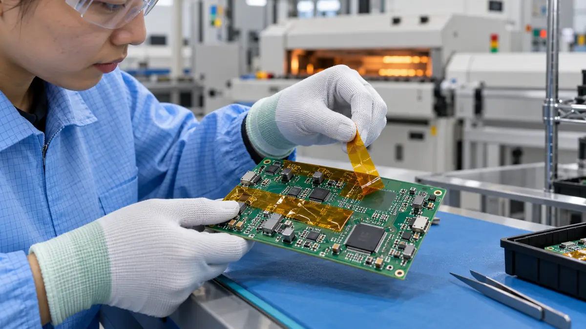
Polyimide tape residue after PCB reflow is prevented by matching the exact adhesive system to the actual board surface, peak temperature, time above temperature, number of cycles, pressure history and removal condition. This guide is for electronics manufacturing engineers, quality teams and buyers who use temporary masking on solder mask, FR-4, gold fingers, connectors or fixtures. A published heat rating is only screening evidence; it does not predict clean removal on every substrate.
First contain affected boards and keep removed tape samples. Then separate true adhesive transfer from flux residue, condensed process contamination, damaged solder mask, or staining. Only change a tape or process variable after the residue has been identified. Technical content reviewed: .
For a general explanation across surfaces and heat processes, start with our polyimide tape residue causes and prevention guide. The workflow here addresses a narrower PCB reflow qualification: board-zone mapping, controlled profile/cycle trials, flux-path checks and the evidence needed before releasing that process.
Map the Residue Mechanism Before Changing Tape
“Sticky after reflow” can describe several different failures. Silicone or acrylic adhesive may transfer, but the visible mark can also be flux, cleaner residue, a softened label coating, dust trapped at the tape edge, or a surface finish altered by heat and peel. Record where the mark begins relative to tape edges, component shadows and airflow. That map often narrows the cause faster than repeating the same run with a different color of tape.
| Observation | Check first | Why it matters |
|---|---|---|
| Tacky film across the full masked area | Adhesive identity, heat exposure, dwell and removal temperature | Consistent transfer may indicate adhesive or process mismatch |
| Deposit concentrated at one edge | Flux path, edge pressure, contamination and airflow | The mask may have trapped or redirected process material |
| Gloss change with no tack | Solder-mask compatibility, peel force and surface damage | Cleaning may worsen a damaged coating |
| Residue only after a second cycle | Cumulative time-temperature history and adhesion build | Peak temperature alone hides repeated exposure |
| Random particles or fibers | Roll handling, converting edge, core and workstation cleanliness | The source may be supply presentation rather than adhesive |
Select the Complete Polyimide Tape Construction
Specify film and adhesive separately
Polyimide film provides thermal stability and a thin barrier, while the pressure-sensitive adhesive controls initial tack, adhesion build, removal force and transfer. A silicone adhesive may support demanding heat exposure; a specialized acrylic construction may be preferred where silicone contamination or low-static requirements matter. Do not infer chemistry from amber color.
Match the contacted surface
FR-4, liquid photoimageable solder mask, gold, nickel, ceramic, silicon, connector resin and labels can respond differently. Request data for the exact tape, then test on production-representative surfaces with the real cure and aging history. A clean result on stainless steel is not proof for a PCB finish.
Control width, die cuts and edge condition
Narrow slit tape can follow a compact keep-out, but extra seams create more edges. A die-cut mask can improve registration when it includes the correct liner, removal tab and dimensional tolerance. Inspect cut edges, roll debris and exposed adhesive because contamination can imitate residue failure.
| Construction choice | Potential advantage | Qualification focus |
|---|---|---|
| Silicone adhesive polyimide | Common high-temperature masking option | Transfer, silicone sensitivity, removal force and downstream cleaning |
| Non-silicone acrylic polyimide | Can reduce silicone-related contamination concerns | Short heat window, surface adhesion, static control and clean removal |
| Low-static construction | Supports defined ESD-sensitive handling | Actual static-dissipative performance through storage and use |
| Kiss-cut mask on liner | Repeatable geometry and placement | Cut depth, liner release, tab design, debris and tolerance |
Build a Trial Matrix That Represents Production
Use a small controlled matrix rather than changing several inputs at once. Include the current tape as a baseline, at least one candidate construction, representative surface lots, minimum and maximum permitted thermal exposure, and the actual removal window. If boards may see two reflow cycles or rework, include that sequence.
Record the thermal history, not just oven settings
Record board-level evidence from the approved profiling method: preheat, time above the process threshold, peak, cooling and cycle count. Oven setpoints do not prove the PCB saw the same history. Also note tape dwell before heating, applied pressure, overlap and whether removal occurs hot, warm or at room condition.
| Trial factor | Minimum coverage | Evidence to retain |
|---|---|---|
| Materials | Tape codes/lots and representative PCB finish lots | COA or supplier identity, board revision and photos |
| Application | Cleanliness, placement, pressure, dwell and overlap | Work instruction and applied-mask inspection |
| Thermal route | Normal and worst permitted profile; repeat cycle if applicable | Profile file and board location |
| Removal | Defined temperature, delay, peel direction and support | Removal time, tape condition and operator record |
| Acceptance | Residue, staining, coating damage and functional checks | Method, limit, result and disposition |
Illustrative Residue-Risk Screen
A simple screening score can keep a trial plan balanced. Assign 0, 1 or 2 points to four factors: thermal exposure beyond the tape's supported evidence, repeated cycles, removal delay outside the supplier's evaluated window, and a sensitive contacted surface. Sum the points only to prioritize trials; it is not a material rating or acceptance standard.
Convert the screen into measurable checks
For each high-scoring combination, define a residue inspection method, magnification if needed, an approved surface analysis or cleanliness test where required, and a functional follow-on check. Do not use an unapproved solvent merely to make the visual mark disappear; that can redistribute contamination or damage the finish.
Control Application, Reflow and Removal
- Confirm the masking drawing. Identify protected zones, forbidden contacts, removal tabs and inspection surfaces.
- Verify material. Match tape code, adhesive family, width or die-cut revision, lot, storage and shelf-life control.
- Inspect the PCB. Reject contamination, damaged solder mask or unapproved surface condition before taping.
- Apply from a datum. Avoid stretching the film, touching adhesive, trapping debris or covering vents and test points.
- Use controlled pressure. Seat the mask without crushing components or forcing adhesive into a connector.
- Inspect before heat. Record edge lift, bubbles, overlap, placement and exposed adhesive.
- Run the approved profile. Capture cycle count and actual representative board history.
- Remove in the validated window. Support the board and peel at the approved angle, speed and temperature.
- Preserve evidence. Retain removed tape, board location, photographs and residue findings.
- Release only after checks pass. Complete workmanship, cleanliness and functional inspections defined by the process owner.
Validate Clean Removal and Board Condition
Clean removal means more than “not sticky to a finger.” Define visible residue, transferred adhesive, staining, surface-energy change, coating lift, particle contamination and electrical or assembly consequences. The method should match the risk of the masked zone. A cosmetic keep-out and a gold contact do not need the same evidence.
Keep material data and acceptance values separate
Manufacturer pages for 3M 5413, 3M 7414 and tesa 4428 describe clean-removal or residue-reduction behavior under product-specific conditions. Those statements support candidate selection; they are not JIAO TAO TAO test results or universal limits. Production acceptance values must come from the customer's released validation plan.
| Validation layer | What to check | Release evidence |
|---|---|---|
| Tape integrity | Lift, shrinkage, tearing, curling and edge movement | Before/after inspection and retained sample |
| Surface condition | Tack, film, particles, stain, coating lift and finish change | Defined inspection or analytical method |
| Assembly | Connector mating, solderability, test access and downstream bonding | Actual follow-on operation result |
| Process window | Surface lot, profile extreme, cycle count and removal delay | Worst-case matrix with traceability |
Troubleshooting Residue and Surface Damage
| Symptom | Check first | Controlled improvement | Revalidation |
|---|---|---|---|
| Adhesive film remains | Tape identity, profile, dwell and removal temperature | Screen a supported adhesive or restore the removal window | Full worst-case route and cleanliness method |
| Solder mask lifts on peel | Mask cure, adhesion build, peel angle and board support | Stop; review PCB finish and lower-removal-force options | Surface integrity plus required electrical checks |
| Residue appears near only one component | Local heat mass, airflow, flux path and mask edge | Correct geometry or process cause under engineering approval | Profile/location repeat and defect map |
| Particles remain after removal | Slit edge, die cutting, handling, core and packaging | Improve converting cleanliness and supply presentation | Particle inspection through unpacking and use |
| Result changes by operator | Pressure, dwell, removal speed, angle and support | Add fixtures, visual standards and a defined removal method | Multi-operator repeatability trial |
Related Products, Articles and Technical Sources
Primary technical references
3M Polyimide Film Tape 5413 describes PCB solder masking and reduced adhesive transfer. 3M Heat Resistive Polyimide Film Tape 7414 describes multiple short reflow cycles and residue-free removal for that product. tesa 4428 lists a polyimide/silicone construction and residue-free removability for its masking uses. Values and claims belong to those exact manufacturer products; qualify the supplied construction independently.
Frequently Asked Questions and RFQ Checklist
Does a 260°C rating guarantee residue-free PCB removal?
No. Peak temperature alone omits time, repeated cycles, surface chemistry, pressure, dwell and removal conditions.
Is silicone adhesive always wrong for electronics?
No. Silicone systems are widely used, but contamination sensitivity and downstream requirements must be defined for the actual assembly.
Should polyimide tape be removed hot or cold?
Use the window validated for the exact tape, surface and process. An uncontrolled delay can change adhesion and peel load.
Can visible inspection alone approve clean removal?
Only when the quality plan says visual inspection is sufficient. Contacts or downstream bonds may require additional cleanliness or functional evidence.
What belongs in a PCB masking RFQ?
Provide PCB finish, mask drawing, contacted materials, profile, cycle count, dwell, removal method, ESD need, cleanliness limits, dimensions, volume and validation plan.
Build a Traceable PCB Masking Trial
Share the PCB finish, masked zone, thermal profile, cycle count, removal window, contamination limits, tape format, dimensions and annual volume. JIAO TAO TAO can prepare slit or converted polyimide masking samples for controlled evaluation.
How to Prevent Wrinkles in PTFE Heat-Sealing Tape
Related Article
Need help choosing the right industrial tape?
Send us your application details, including temperature, surface material, size, quantity and current problem. Our team will help recommend a suitable tape material or custom die-cut solution.

simon@jiaotaotao.com


+86-136 1277 5969


+86-136 1277 5969
