
Polyimide Tape for PCB Reflow Thermocouple Attachment
Technical Insights · SMT Process Engineering
Polyimide Tape for PCB Reflow Thermocouple Attachment
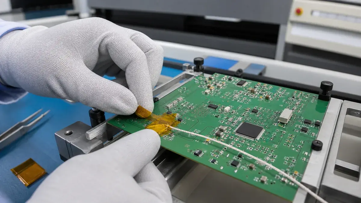
Polyimide tape for PCB reflow thermocouple attachment can hold fine-gauge sensor wire close to a designated measurement point during a profiling run. Accurate data still depends on bead contact, attachment mass, wire routing, board loading, profiler setup, and a documented method—not on the tape alone.
Quick Answer
Small polyimide tape patches are often evaluated as a low-profile way to retain thermocouple leads during PCB reflow profiling. The bead or junction must remain in intimate contact with the defined feature throughout transport and heating. Tape should secure the wire without insulating the measurement point so heavily that the recorded curve no longer represents the target solder joint, component body, pad, or board region.
Define What the Thermocouple Must Measure
A reflow profile may be used to understand a thermally heavy termination, a small heat-sensitive component, a shadowed area, a board edge, or the hottest and coldest credible locations. Placing a thermocouple “near” the target is not enough. The process engineer should state whether the junction contacts solder, copper, component body, laminate, or another defined surface and how that location relates to acceptance criteria.
| Measurement target | Main attachment concern | Documentation point |
|---|---|---|
| Solder joint or pad | Bead must contact the intended metal without bridging conductors | Photo, reference designator, and exact junction position |
| Component body | Tape and bead mass can alter surface response | Body face, edge setback, and attachment footprint |
| Board laminate | Local copper density changes response | Layer region and distance from nearby features |
| Thermally heavy terminal | Wire strain may pull the bead away during transport | Strain-relief point and route |
| Small sensitive part | Patch may cover the part or trap heat | Maximum patch size and approved contact face |
Select Polyimide Tape for the Profiling Run
Evaluate the complete construction
Polyimide film contributes dimensional stability and thin handling at elevated process temperatures. Silicone pressure-sensitive adhesive is common in many high-temperature polyimide tapes, but adhesive coat weight and formulation influence initial tack, holding power, residue, and removal. Film thickness also changes stiffness and the ease of forming a small patch around a wire.
Use the real thermal history
Record the measured board profile, not only the oven setpoint. Include preheat, time above the relevant temperature, peak, cooling rate, and the number of passes. A tape intended for one profiling run may not be suitable for repeated reuse. Confirm whether it is removed hot, warm, or after full cooling and inspect the actual solder mask and component surfaces.
Control contamination and ESD
Handle the profiling board according to the site’s ESD and cleanliness procedures. Do not place adhesive on unapproved contacts, optical surfaces, vents, labels, or connector interfaces. Any residue, film fragment, or lifted coating can invalidate the board for further evaluation.
| Selection input | What to record | Why it matters |
|---|---|---|
| Tape construction | Product code, film, adhesive, thickness, width, and lot | Defines heat response and traceability |
| Board surface | Solder mask, finish, cleanliness, components, and labels | Changes adhesion and removal risk |
| Thermal profile | Actual peak, dwell, ramp, cooling, and pass count | Screens the complete construction |
| Sensor system | Thermocouple type, wire gauge, bead, connector, and channel | Controls response and repeatability |
| Removal rule | Temperature, direction, speed, and board disposition | Reduces damage and preserves evidence |
Design a Low-Mass, Stable Attachment
The smallest patch that reliably controls the wire is often preferable, but “small” must be defined. One method may use a primary contact technique approved by the profiling procedure and a separate polyimide patch a short distance away for strain relief. Another may use the tape itself to maintain bead contact. Do not assume these methods produce interchangeable data.
Route wires in the conveyor direction when practical, with gradual bends and enough slack to avoid pulling the bead. Keep the bundle away from moving rails, nozzles, sensors, and board support hardware. Multiple overlapping patches can create a thermal blanket or snag point, so specify maximum layers and patch locations.
Recommended Profiling Workflow
- Release the plan. Identify target locations, channels, acceptance limits, and profile purpose.
- Verify materials. Record board revision, thermocouples, profiler, tape code, and lot.
- Inspect the board. Check solder mask, components, pads, contamination, and damage.
- Prepare the junction. Form and position the bead using the approved method.
- Apply the patch. Use the specified size and pressure without shifting the junction.
- Add strain relief. Secure the lead at the documented distance and direction.
- Route all wires. Prevent crossings, tight bends, rail contact, and conveyor snagging.
- Photograph the setup. Capture every junction and its reference location before the run.
- Run and review. Check live channels for open circuits, spikes, and implausible curves.
- Remove and inspect. Follow the released peel method and document board/tape condition.
Check Repeatability Before Using the Data
Repeat selected measurements with fresh thermocouples or attachments to estimate method variation. Compare attachment photos, bead position, patch geometry, and curves. If two nominally identical setups produce materially different results, investigate the measurement system before changing the oven recipe.
- Confirm every channel responds smoothly and remains identified from board to software.
- Compare critical locations over repeated passes under the same board-loading condition.
- Record whether the profiling board is sacrificial and how many cycles it has completed.
- Inspect for bead lift, wire movement, residue, discolored film, damaged solder mask, or displaced components.
- Revalidate after tape, thermocouple, board revision, fixture, oven, or attachment-method changes.
Troubleshooting Profile Anomalies
| Observed issue | Check first | Corrective direction |
|---|---|---|
| Sudden temperature spike | Loose junction, electrical noise, connector, or wire contact | Inspect the channel and rebuild the attachment |
| Curve is slower than expected | Oversized tape patch, multiple layers, or bead not on target | Reduce attachment mass and verify contact |
| Thermocouple opens during transport | Wire route, strain relief, rail contact, and junction fatigue | Revise routing and support without covering the target |
| Tape lifts in the oven | Surface contamination, pressure, patch geometry, and heat history | Requalify preparation and tape construction |
| Residue or mask damage after peel | Adhesive, dwell, repeated passes, cooling, and peel direction | Change the qualified tape/removal window |
Related Products and Articles
Frequently Asked Questions
Can polyimide tape alone guarantee accurate thermocouple readings?
No. Accuracy depends on the junction, contact method, patch mass, wire routing, profiler, calibration, board loading, and repeatable documentation.
Should the tape cover the thermocouple bead?
Only if the approved profiling method requires it. Covering the bead can improve retention but may add insulation and change the measured response.
Can the same taped thermocouple be reused for many profiles?
Do not assume reuse is acceptable. Heat cycling can change the wire, junction, tape adhesion, residue, and board condition. Define and verify a maximum use count.
Why use a separate strain-relief patch?
It can reduce wire load at the measurement junction while keeping extra tape mass away from the target. The distance and route should be standardized.
What belongs in a tape RFQ?
Provide the PCB surface, peak and dwell, pass count, thermocouple wire size, patch dimensions, removal condition, residue limit, width, quantity, and validation plan.
Standardize the Thermocouple Attachment
Share the board surface, target points, thermocouple construction, measured profile, patch geometry, removal stage, and cleanliness limit. JIAO TAO TAO can help shortlist a polyimide tape construction for controlled profiling trials.
Discuss PCB reflow profilingPTFE Tape for Textile Seam-Sealing Machine Guide Surfaces
PTFE Tape for Laminating Machine Heater Shoe Protection
Related Article
Need help choosing the right industrial tape?
Send us your application details, including temperature, surface material, size, quantity and current problem. Our team will help recommend a suitable tape material or custom die-cut solution.

simon@jiaotaotao.com


+86-136 1277 5969


+86-136 1277 5969
