
Polyimide Tape for Lithium Battery Tab Root Insulation
Product Guides · Battery Assembly Insulation
Control coverage without blocking the weld.
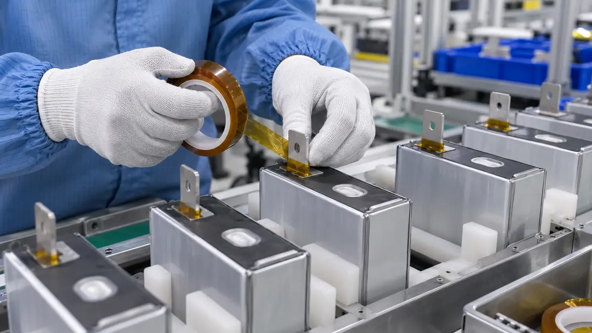
Polyimide tape for lithium battery tab root insulation can create a thin local barrier where a conductive tab exits a cell and enters a module connection area. The tape is not a universal battery-safety component: the complete film, adhesive, overlap, cell surface, electrical clearance, electrolyte exposure, joining process, and final assembly must be qualified by the battery designer.
Quick Answer
Choose a battery-grade polyimide tape only after the tab-root function and exposure are defined. An external module-assembly wrap, an in-cell tab tape, a temporary welding mask, and a service-insulation patch are different applications. They can require different adhesives, cleanliness limits, release liners, chemistry screening, and lifetime evidence even when the backing looks similar.
This guide is for battery design, quality, and manufacturing engineers comparing external tab-root insulation candidates. Use drawings, inert mock-ups, and approved de-energized fixtures for the geometry study below; cell handling, joining, electrical testing, and internal-cell materials qualification belong to trained personnel under the battery owner's released procedures. Technical content reviewed: .
Define the Tab-Root Insulation Boundary
Start with the cell and module drawing, not a roll width. Record the cell format, tab metal, tab thickness, edge condition, bend radius, busbar geometry, nearby conductive hardware, available clearance, and whether the tape remains for product life. The tab root may move during forming or joining; an apparently correct wrap can shift into the weld area or create an unwanted step beneath a busbar.
| Design input | What to define | Why it matters |
|---|---|---|
| Cell interface | Pouch, prismatic, or cylindrical design; external or internal location | Changes chemistry, cleanliness, and lifetime requirements |
| Tab geometry | Metal, thickness, root radius, burr control, bend, and datum | Controls coverage and puncture risk |
| Electrical design | Voltage, clearance, creepage, adjacent conductors, and fault strategy | Sets assembly-level insulation requirements |
| Joining process | Method, heat path, tooling, inspection, and keep-out | Prevents tape from contaminating or obstructing the joint |
| Environment | Electrolyte possibility, humidity, fluids, temperature, and aging | Determines adhesive and backing qualification |
Select the Complete Tape Construction
Polyimide backing
Backing thickness affects conformability, edge coverage, cut resistance, stiffness, and the height added to the stack. A thicker film may resist handling damage but can be harder to wrap around a narrow radius. A thinner film may fit a tight space but should not be assumed to tolerate a burr or repeated flexing.
Adhesive system
Battery assembly may call for an acrylic, silicone, or specialized adhesive selected for the real surface and exposure. Do not infer electrolyte compatibility, low ionic contamination, flame behavior, or long-term adhesion from the word “polyimide.” Obtain the relevant material evidence and repeat tests on the production cell surface.
Liner, slitting, and cleanliness
A liner-backed slit roll or die cut can reduce adhesive handling and support automated placement. Define edge quality, particulate limits, roll winding, splice rules, core, packaging, and storage. The cleanest film specification can still fail if slitting debris, glove contact, or an uncontrolled work surface contaminates the adhesive.
Compare Tab-Root Tape Formats
| Format | Best fit | Main control point |
|---|---|---|
| Narrow slit roll | Manual wrapping and changing prototypes | Width tolerance, tension, overlap, and end location |
| Precut strip | Stable length with simple placement | Cut edge, orientation, and piece accountability |
| Kiss-cut patch | Repeated geometry and fixture placement | Liner release, datum, corner radius, and tab access |
| Shaped wrap | Complex root geometry or defined pull tabs | Drawing tolerance and wrinkle-free forming |
| Carriered multi-part set | Several cells placed in one station | Pitch, carrier stability, and missing-piece detection |
Format should reduce operator variation without hiding critical features. A die cut may improve repeatability, but it also requires stable geometry and controlled registration. Manual slit tape remains useful during development if overlap, tension, and end position are documented.
Worked Coverage Check for a Flat Tab-Root Patch
Convert the drawing into two independent checks: the smallest coverage remaining over the protected zone and the smallest clearance remaining to the joining keep-out. A patch that passes one can still fail the other. For a centered, flat patch, let W be nominal patch width, T the maximum protected-zone width, and e the combined placement and cut-edge location error toward either side; minimum side coverage is (W − T) / 2 − e. This simplified check does not model a folded wrap, curved root, tab motion, or electrical creepage.
| Record | Enter before sampling | Decision it supports |
|---|---|---|
| Interface and geometry | External location; drawing revision; maximum tab zone; minimum keep-out; radius; relevant datum tolerances | Can every tolerance condition meet coverage and access simultaneously? |
| Complete material stack | Film, adhesive, total thickness without liner, chemistry evidence, traceable tape code | Does the actual supplied construction fit the available stack height? |
| Candidate A versus B | Same geometry and fixture; change only the documented adhesive or film construction | Is the observed improvement attributable to a controlled variable? |
| Sampling conditions | Surface lots; geometry extremes; approved conditioning; equipment; operator; sample count set by the quality plan | Does evidence represent the intended process rather than one convenient part? |
| Disposition | Retain / reject / investigate; failed requirement; evidence file; next controlled change | Can another engineer reproduce the decision? |
Material names cannot close this worksheet. For example, 3M Polyimide Film Electrical Tape 1205 uses an acrylic adhesive, while Nitto P-222 polyimide tape uses a silicone adhesive. These are evidence that adhesive construction differs within the polyimide family, not recommendations or battery approvals for either product.
Recommended Application Workflow
- Confirm the released drawing. Identify the insulation zone, weld keep-out, datum, and final overlap.
- Match the material. Verify tape code, lot, width, thickness, adhesive, liner, and shelf-life controls.
- Inspect the cell and tab. Stop for burrs, contamination, damage, moisture, or geometry outside the released condition.
- Control handling. Use the approved gloves, work surface, tools, and protective packaging.
- Place from a stable datum. Avoid stretching the film or touching the adhesive.
- Form the wrap. Use the qualified pressure, overlap, bend sequence, and end orientation.
- Inspect before joining. Check weld clearance, wrinkles, edge lift, fragments, and piece count.
- Run the approved joining process. Keep heat, energy, tooling, and cleaning within the released window.
- Inspect after joining. Check displacement, discoloration, damage, residue, and connection access.
- Release by assembly evidence. Apply electrical, mechanical, environmental, and safety tests defined by the product owner.
Validate the Tape in the Real Battery Assembly
Flat peel coupons can compare lots, but they cannot reproduce a thin metal tab, root radius, cell-top coating, compression, busbar joint, chemistry, or production handling. Trials should include representative surface lots, geometry extremes, operators, equipment settings, storage conditions, and aging paths.
| Validation group | Observe | Release evidence |
|---|---|---|
| Placement | Coverage, overlap, wrinkle, end position, and weld keep-out | Drawing, gauge, vision standard, or approved image |
| Materials | Adhesion, contamination, chemistry, moisture, and aging | Application-specific test plan and supplier evidence |
| Process | Handling, joining heat, cleaning, compression, and rework | Production-equivalent pilot build |
| Electrical | Insulation design, clearance, creepage, and required tests | Battery engineering acceptance criteria |
| Assembly | Busbar fit, tab movement, vibration, thermal cycling, and service condition | Cell, module, and pack qualification as applicable |
Tab-Root Acceptance Record Template
For each trial retain: part and drawing revision | tape code and lot | cell-surface lot | fixture revision | measured minimum coverage in mm | measured minimum joining clearance in mm | wrinkle / cut / edge-lift inspection result | conditioning and test-plan revision | requirement and measured result | photo IDs | reviewer | disposition. Record observations before and after the qualified process exposure. Enter the engineering-approved limit before testing, leave untested fields marked “not tested,” and hold the candidate when any required result is absent; a good-looking patch is not release evidence.
Troubleshoot Without Guessing
| Symptom | Check first | Controlled action | Required recheck |
|---|---|---|---|
| Edge lifts at the same root corner | Root radius, tab springback, wrap tension, and surface condition against the drawing | On an inert fixture, compare the approved baseline with one revised geometry or application variable | Minimum coverage, edge lift after conditioning, and stack fit |
| Coverage passes but tape enters the weld keep-out | Datum registration and the complete tolerance stack | Correct the patch shape or fixture datum through engineering change control | Both coverage and minimum joining clearance at geometry extremes |
| Film cut or puncture at a metal edge | Burr condition, tool marks, and contact points | Contain nonconforming parts and correct the edge or tooling to the released condition | Visual integrity plus electrical tests specified by battery engineering |
| Residue, swelling, or lift after exposure | Exact adhesive code, surface lot, storage, and approved chemistry exposure record | Hold the candidate and obtain application-specific compatibility evidence | The relevant materials, contamination, and assembly qualification sequence |
Do not solve every defect by increasing adhesion or adding layers. Extra wraps can reduce clearance and obstruct joining. If the root cause remains uncertain, preserve the affected sample, photographs, lot information, and exposure history for the battery engineering team.
Related Products and Articles
Technical Sources and Scope
tesa's battery energy-storage application overview separates module electrical insulation, in-cell fixation, and assembly bonding. That distinction supports defining the location and function before selecting a tape. The linked 3M and Nitto product pages support the adhesive-family comparison above; their data and claims apply to their own identified products. This guide's worksheet and calculations are original engineering examples, not measured JIAO TAO TAO performance or a substitute for a released battery design.
Frequently Asked Questions
Is every amber polyimide tape suitable for lithium battery tab insulation?
No. Appearance does not establish adhesive chemistry, cleanliness, electrolyte compatibility, aging behavior, electrical performance, or suitability for a specific cell design.
Can the tape overlap the battery-tab weld area?
It should remain outside any joining and inspection keep-out defined by battery engineering. The released drawing must control the boundary.
Is a thicker polyimide tape always safer?
No. Thickness changes conformability, step height, stiffness, clearance, and puncture resistance. Select the complete stack against the assembly requirements.
Should the tape use a release liner?
A liner can protect the adhesive and enable die-cut or automated placement, but its release force, static control, cleanliness, and removal method must fit the process.
What information belongs in an RFQ?
Provide the cell and tab drawing, location, surface, tape function, width and thickness limits, adhesive preference, exposure, joining method, cleanliness controls, volume, and qualification plan.
Prepare a Controlled Battery Tab-Tape Trial
Share the cell and tab drawing, external or internal location, surface, insulation boundary, weld keep-out, chemistry exposure, temperature history, target width and thickness, placement method, annual volume, and acceptance plan. JIAO TAO TAO can prepare slit or die-cut polyimide tape samples for engineering evaluation.
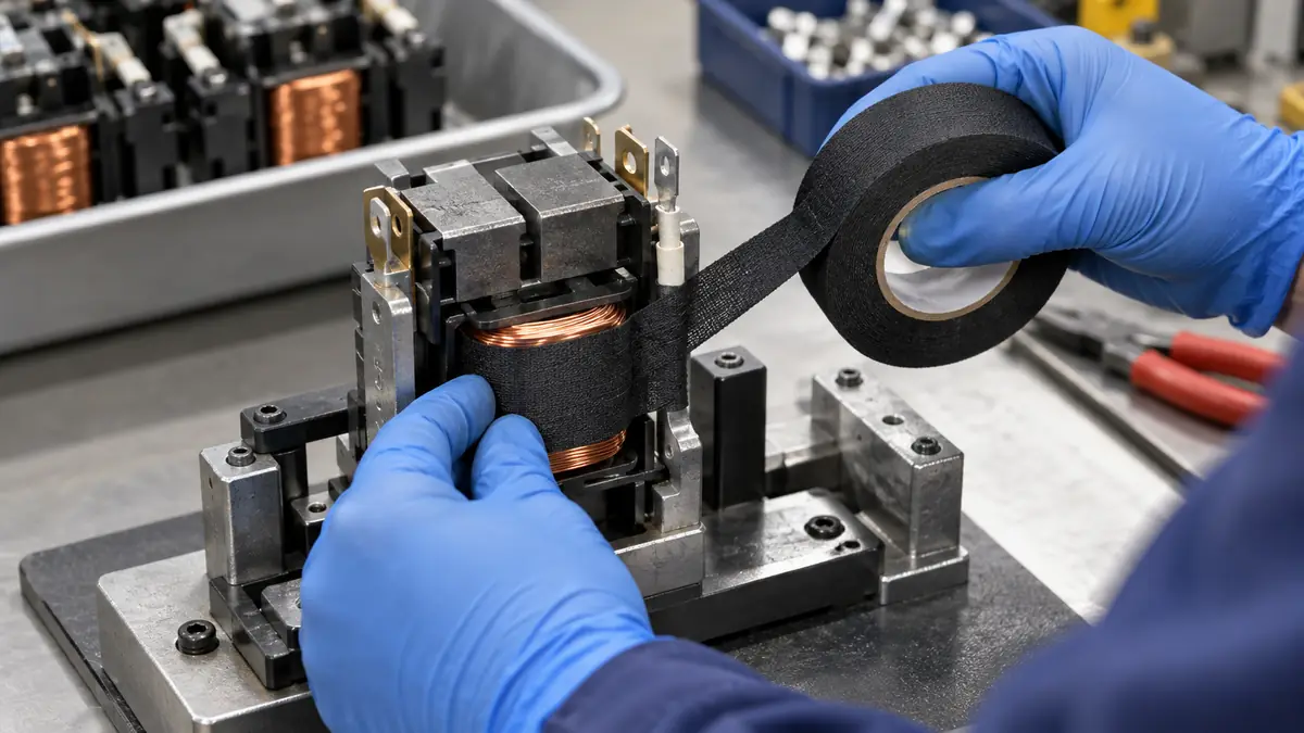
Acetate Cloth Tape for Industrial Contactor Coil Finishing
Related Article
Need help choosing the right industrial tape?
Send us your application details, including temperature, surface material, size, quantity and current problem. Our team will help recommend a suitable tape material or custom die-cut solution.

simon@jiaotaotao.com


+86-136 1277 5969


+86-136 1277 5969
