
Polyimide Tape for Ceramic Heater Thermistor Lead Fixation
Application Solutions · Industrial Heaters
Polyimide Tape for Ceramic Heater Thermistor Lead Fixation
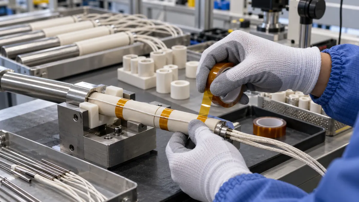
Polyimide tape can secure a thermistor lead to an approved cool-side ceramic heater surface during assembly, but it must not be treated as the temperature sensor, primary electrical barrier, strain relief or a repair for a damaged heater. The correct construction and tape location must be qualified with the actual heater, lead insulation, thermal profile and control system.
Quick Answer
Use polyimide tape for ceramic heater thermistor lead fixation only where the heater or equipment design defines a suitable tape zone. Keep the tape away from the active heating face, exposed conductors, sharp ceramic edges and any surface needed for heat transfer, clamping or bonding. Fix the lead without crushing its insulation or moving the sensing element, then validate the completed heater through the required electrical, thermal, mechanical and control-response tests.
Define What the Tape Must Do
A ceramic heater assembly may include the ceramic element, electrodes, bus connections, thermistor or thermocouple, lead insulation, terminals, mounting hardware and a control circuit. A small tape strip can be useful as an assembly aid or local lead retainer. It cannot replace the heater designer's creepage and clearance, sensor attachment method, over-temperature protection, connector strain relief or guarding.
State whether the tape remains for service life or is removed after another retention step. Identify the exact lead segment it holds, the permitted movement, the sensor's thermal response target and the surfaces that must remain visible for inspection. This prevents a convenient tape patch from acquiring an undefined safety function.
| Possible function | What tape may support | What still requires separate design |
|---|---|---|
| Assembly positioning | Keep a light lead on a released route before final assembly | Permanent strain relief and connector retention |
| Local insulation support | Cover an approved low-stress crossing | Required dielectric spacing and primary insulation |
| Sensor location aid | Reduce lead movement near a defined sensor position | Sensor coupling, calibration and control response |
| Temporary process hold | Hold a lead during potting, bonding or enclosure assembly | Cure compatibility and final mechanical support |
| Service identification | Maintain a visible routed path when the design permits | Labels, traceability and inspection instructions |
Select the Complete Tape Construction
Compare film and total thickness
Thin polyimide film can follow a smooth ceramic base with low added profile. Total thickness includes the adhesive and determines the installed step, bend stiffness and space used beneath a cover or clamp. A thicker tape is not automatically safer; it can lift at a small radius or change the lead path.
Choose the adhesive deliberately
Silicone adhesive is commonly screened for elevated-temperature processing, while acrylic constructions may suit different bonding or aging priorities. Obtain data for the exact product and evaluate adhesion on the actual ceramic glaze, metal feature, lead jacket and any coating. Do not assume that every ceramic surface has the same surface energy or cleanliness.
Review contamination and removability
If the tape is temporary, define peel direction, removal temperature and residue limits. If it remains in the assembly, consider adhesive flow, outgassing, migration and interaction with potting compounds, thermal grease, cleaners or conformal coatings. Color alone does not confirm construction or heat performance.
| Selection input | Information to provide | Why it changes the choice |
|---|---|---|
| Heater surface | Ceramic type, glaze, roughness, coatings and cleanliness | Controls wet-out and edge stability |
| Thermal duty | Measured local temperature, ramp, dwell, cycles and cool-down | Separates process peaks from long-term exposure |
| Lead system | Conductor size, jacket, sensor type, bend radius and movement | Prevents compression, abrasion and response changes |
| Electrical duty | Voltage, spacing, fault strategy and required tests | Defines insulation-system validation |
| Assembly | Tape dimensions, cover clearance, pressure, cure and service access | Connects the tape to the full manufacturing process |
Design the Lead Route and Tape Geometry
Route the thermistor lead along a supported, relatively uniform surface that is explicitly outside prohibited hot, clamping and bonding zones. Avoid drawing the wire across a sharp ceramic edge or under a screw head. The sensor bead or sensing junction should stay at the location defined by the thermal design; pulling the lead to make the tape lie flat can shift the measurement point.
Use a strip width and length that seat the lead without excessive exposed adhesive. Rounded strip corners or a die-cut shape may reduce snagging. Define whether the tape crosses the lead once, forms a short saddle or follows another released pattern. Excessive wrapping can thermally insulate the sensor region and slow response, while a very small tab may lift during cycling.
Recommended Application Workflow
- Verify the build. Match heater, sensor, lead, tape and drawing revisions.
- Confirm isolation. Work only on a de-energized, cool assembly under the approved procedure.
- Inspect components. Reject cracked ceramic, damaged insulation, loose terminals or contaminated surfaces.
- Prepare the approved area. Use only the released cleaning method and let it dry.
- Route without stress. Maintain bend radius and keep the sensing element in position.
- Apply the tape. Seat it with controlled pressure and without stretching the film.
- Check boundaries. Confirm clearance from the active face, contacts, clamps and bond zones.
- Inspect the finished profile. Look for wrinkles, trapped debris, sharp steps and lifted corners.
- Record traceability. Capture tape lot, dimensions, location and operator or machine.
- Run released tests. Complete electrical, thermal, response and fit checks.
Validate the Heater as a Complete System
Qualification should use production-intent heaters, leads, sensors, fixtures, enclosures and control settings. Reproduce minimum and maximum credible tape placement, surface condition, application pressure and aging. Monitor local temperature rather than relying only on controller setpoint. The tape may change heat flow or sensor response even when it still looks intact.
| Validation area | What to observe | Example release evidence |
|---|---|---|
| Thermal response | Warm-up, overshoot, sensor lag and cycle repeatability | Approved control limits on representative builds |
| Tape condition | Lift, shrinkage, bubbling, discoloration and adhesive movement | Visual and dimensional acceptance criteria |
| Lead integrity | Jacket marks, bend stress, abrasion and terminal movement | Inspection plus required pull or flex checks |
| Electrical safety | Spacing, insulation and leakage or dielectric checks | Product-owner test plan and applicable standard |
| Assembly fit | Cover clearance, clamp seating, wire routing and service access | Released drawing and functional assembly check |
Diagnose Failure Patterns
Edge lift can come from contamination, a rough glaze, stored tension, insufficient pressure, a sharp tape corner or thermal expansion. Discoloration or brittle film may indicate a local hot spot beyond the qualified condition. Adhesive movement can result from the exact chemistry, excessive dwell, pressure or contact with another material. A slow or unstable temperature reading may be a sensor-location, coupling, wiring or control issue rather than a tape adhesion problem.
Preserve the failed assembly and compare the first point of change with the drawing and temperature history. Do not add more layers until the cause is known; extra tape changes thickness, heat transfer and inspection access. Change one controlled factor and repeat the complete validation sequence.
Related Products and Articles
Frequently Asked Questions
Can polyimide tape touch the active ceramic heating surface?
Only if the released heater design explicitly permits it and the exact tape has passed representative testing. Many assemblies should keep tape on a defined cool-side route so it does not disturb heat transfer or exceed the adhesive's usable condition.
Does polyimide tape replace thermistor cement?
No. A tape strip and a thermally conductive sensor attachment material perform different functions. Use the sensor mounting method specified by the heater and control-system design.
Is silicone-adhesive polyimide tape always best?
No single adhesive is universal. Silicone systems are commonly screened for heat, but the substrate, dwell, service life, contamination limits and removal need must determine the choice.
Can more tape improve electrical insulation?
Not automatically. Additional layers can create ridges, trap heat, hide damage and alter spacing. Electrical insulation must be validated as a complete system against the released design requirements.
What information belongs in an RFQ?
Provide the heater drawing, approved tape zone, ceramic finish, local thermal history, sensor and lead materials, voltage, tape dimensions, permanent or temporary use, quantity and validation requirements.
Plan a Ceramic Heater Lead-Fixation Trial
Share the heater assembly drawing, sensor location, lead construction, ceramic surface, measured temperature profile, tape-zone dimensions, electrical requirements, downstream materials and annual demand. JIAO TAO TAO can prepare polyimide tape rolls or converted pieces for your controlled engineering evaluation.
Discuss polyimide tape for heater sensor leads
PTFE Tape for ACF Bonding Thermode Release Surfaces
Related Article
Need help choosing the right industrial tape?
Send us your application details, including temperature, surface material, size, quantity and current problem. Our team will help recommend a suitable tape material or custom die-cut solution.

simon@jiaotaotao.com


+86-136 1277 5969


+86-136 1277 5969
