
Custom Die-Cut Tape for EV Charging Port Gasket Positioning
Application Solutions · EV Charging Hardware
Custom Die-Cut Tape for EV Charging Port Gasket Positioning
Custom die-cut tape for EV charging port gasket positioning can hold a converted gasket or seal component to a defined housing datum during subassembly. The adhesive geometry must preserve connector openings, drainage, fasteners, compression lands, sensing features, and service access while the finished inlet is validated as a complete system.

Quick Answer
Use a custom die-cut adhesive only after defining whether it permanently bonds a separate gasket, temporarily locates a compressible seal, retains a dust barrier during handling, or supports another released function. The adhesive must not be assumed to create the charging port’s environmental seal by itself. Compression, housing geometry, gasket material, fasteners, mating panels, drainage, and vehicle-level validation determine the final interface.
Define the Charging-Port Gasket Joint
A charging inlet may combine a molded connector housing, mounting flange, door or bezel, lighting features, communication and power contacts, temperature sensing, locking hardware, drain paths, harness interfaces, and one or more seals. A converted adhesive layer can simplify handling, but it must stay clear of electrical contacts, connector cavities, pressure-relief or drainage features, fastener holes, latch travel, and any surface reserved for a different sealant or coating.
Clarify which component is the primary environmental barrier. If a compressible gasket makes the seal, the tape may only hold that gasket until the housing is clamped. If the die-cut adhesive itself is part of the sealed bond line, its carrier, thickness, continuity, edges, splices, and long-term exposure become functional design inputs. The drawing and test plan should distinguish these roles so purchasing does not substitute materials by appearance.
| Joint input | What to document | Why it matters |
|---|---|---|
| Assembly architecture | Housing, gasket, bezel, panel, fasteners, harness, and service sequence | Defines what the adhesive holds and when it is loaded |
| Substrate surfaces | Plastic family, coating, metal finish, texture, curvature, and release agents | Controls wet-out and bond consistency |
| Functional zones | Seal land, contact openings, drains, vents, sensors, latch, and screw bosses | Creates mandatory adhesive keep-outs |
| Environmental route | Assembly fluids, wash, temperature, humidity, splash, dust, and service chemicals | Screens material compatibility and aging |
| Acceptance plan | Position, compression, fit, leak or ingress tests, electrical checks, and serviceability | Connects the die cut to finished-inlet performance |
Select the Adhesive and Carrier
Substrate compatibility
Charging-inlet housings and surrounding trim can use engineering plastics, coated metals, elastomers, foams, and treated surfaces. Surface energy, texture, molding additives, contamination, and curvature affect adhesive wet-out. Test the exact adhesive on production-molded and finished parts rather than relying only on smooth laboratory panels.
Film, foam, or transfer construction
A thin film carrier can provide dimensional stability and clean converting where the joint is flat. A foam carrier can accommodate selected gap variation and distribute pressure, but thickness also affects compression and fit. Transfer adhesive offers a low-profile bond but can be harder to handle around narrow webs. Choose construction from the joint mechanics, not from a generic “automotive tape” label.
Liner and assembly behavior
The liner is part of the production system. Its stiffness, release level, transparency or color, split pattern, pull tabs, and peel direction affect placement and whether operators touch or distort the gasket. For automation, include web width, pitch, roll direction, matrix removal, sensor marks if approved, and the minimum web strength required by the feeding equipment.
| Construction option | Potential fit | Main control point |
|---|---|---|
| Double-coated film tape | Thin, dimensionally controlled gasket attachment | Surface conformity, shear, edge contact, and film stiffness |
| Double-coated foam tape | Selected gap filling or stress distribution | Compression, recovery, thickness, water path, and creep |
| Transfer adhesive | Low-profile gasket lamination | Handling, unsupported adhesive, stretching, and liner release |
| Single-sided retention patch | Local temporary hold during assembly | Whether the patch remains and how load transfers after clamping |
| Gasket prelaminated by converter | Controlled one-part installation | Lamination quality, registration, storage, packaging, and traceability |
Engineer the Die-Cut Geometry
Build the adhesive path from the functional keep-outs outward. Apply defined clearances around connector cavities, contacts, mounting holes, latch features, drains, light guides, labels, and pressure or temperature sensors. Avoid narrow adhesive bridges that tear during matrix removal or application. Rounded internal and external corners can reduce stress concentration and improve converting stability, subject to the gasket and housing drawing.
Choose a locating strategy that production can see and measure. Registration holes, asymmetric shapes, datum notches, carrier windows, and extended liner tabs can prevent rotation or mirror-image errors. If the gasket must be placed into a recess, account for draft, ribs, texture, depth, and tool access. Control the combined tolerance of the housing, gasket, adhesive conversion, fixture, and operator or automation—not only the die-cut drawing.
Controlled Gasket-Positioning Workflow
- Confirm the released assembly. Verify inlet, gasket, adhesive part, drawing revision, fixture, and work instruction.
- Inspect the housing. Check molding condition, coating, texture, flash, damage, contamination, drains, and functional openings.
- Condition materials. Follow approved storage and assembly temperature rules for the housing, gasket, tape, and liner.
- Clean as specified. Use only the released preparation method and allow the bond land to dry completely.
- Locate from the datum. Use the fixture, holes, notches, or housing features designed into the converted part.
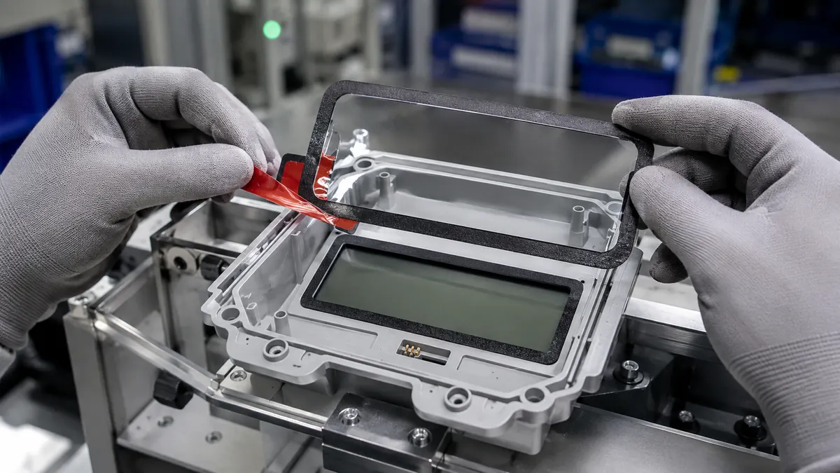
- Peel in the controlled direction. Remove the liner without stretching the gasket or touching the adhesive.
- Apply uniform pressure. Press the complete bond path using the qualified tool and sequence.
- Inspect before closure. Check position, wrinkles, exposed adhesive, liner fragments, keep-outs, drains, and pull tabs.
- Complete the inlet assembly. Install mating parts and fasteners with the released torque and compression sequence.
- Run final tests. Verify fit, seal or ingress performance, connector operation, locking, electrical checks, and service access.
Validate the Complete Charging-Inlet Assembly
Qualification should include production housings and gaskets across tolerance limits, the exact adhesive and liner, realistic storage, operator or automation variation, the shortest and longest permitted dwell before closure, the complete fastener sequence, and representative environmental exposure. Include service removal where the assembly is repairable; a strong initial bond may complicate disassembly or damage the housing.
| Validation group | What to observe | Release question |
|---|---|---|
| Converting and incoming | Dimensions, adhesive registration, cut quality, liner, matrix, contamination, and packaging | Does the supplied part match the released drawing? |
| Application | Datum, rotation, wrinkles, stretch, pressure, keep-outs, and liner removal | Can the gasket be positioned repeatably? |
| Closure and compression | Fastener sequence, compression map, squeeze-out, edge lift, housing distortion, and fit | Does assembly create the intended interface? |
| Environment | Temperature cycling, humidity, splash, dust, fluids, vibration, and aging as applicable | Does the complete joint remain acceptable? |
| Charging and service | Connector mating, locking, sensing, heating checks, drainage, inspection, and removal | Does the finished inlet perform and remain serviceable? |
Troubleshoot Gasket-Positioning Defects
A gasket that shifts during closure may have insufficient initial wet-out, a contaminated or textured bond land, an unstable carrier, poor pressure, stored stretch from liner removal, or a fixture that does not support the part. Edge lift around a corner can involve excess stiffness, a small radius, housing draft, tension in the gasket, or low contact pressure. Uneven compression may come from the gasket or housing tolerances, adhesive thickness, fastener sequence, or incorrect registration.
Do not solve every issue with a thicker or stronger tape. Extra foam thickness can change compression, create a water path, or distort fit, while higher adhesion can make service removal destructive. Separate positioning failures from primary sealing or mechanical-joint failures, measure actual parts, inspect the compression path, and compare controlled geometry or fixture changes before changing adhesive chemistry.
↑ Back to contentsRelated Products and Articles
Frequently Asked Questions
Can die-cut tape position a gasket on an EV charging port?
Yes, when the adhesive, gasket, housing, geometry, liner, assembly pressure, closure sequence, environment, and finished inlet tests are qualified together.
Does the tape provide the charging port’s waterproof seal?
Not automatically. The primary seal may depend on gasket compression, housing geometry, fasteners, panel interfaces, or another sealing material. Define the tape’s role explicitly.
Should the adhesive cover the complete gasket?
Coverage depends on the gasket design and functional zones. Full coverage can improve handling but may interfere with compression, drainage, or service, so use the released drawing.
Why use a split liner or pull tab?
Controlled liner features can reduce adhesive handling, limit gasket stretch, support staged placement, and help operators remove every liner segment before closure.
What information belongs in an RFQ?
Provide the housing and gasket drawings, substrates, functional keep-outs, tape role, environmental and fluid exposures, liner and assembly method, annual volume, packaging, and validation plan.
Prepare a Charging-Port Gasket Trial
Share the charging-inlet housing and gasket drawings, mating panel, substrate materials, adhesive zones and keep-outs, compression and fastening design, environmental exposure, liner preference, assembly method, service route, annual quantity, packaging needs, and finished-product tests. JIAO TAO TAO can help develop converted tape concepts for controlled evaluation.
Discuss EV charging-port gasket positioning
PET Silicone Tape for Powder-Coat Drain-Slot Masking
Related Article


Need help choosing the right industrial tape?
Send us your application details, including temperature, surface material, size, quantity and current problem. Our team will help recommend a suitable tape material or custom die-cut solution.

simon@jiaotaotao.com


+86-136 1277 5969


+86-136 1277 5969
