
Polyimide Tape for Induction Heating Coil Insulation
Polyimide Tape for Induction Heating Coil Insulation
Polyimide tape for induction heating coil insulation can protect selected lead junctions, support points, sensor wires, and auxiliary electrical interfaces where a thin, heat-resistant insulating film is appropriate. It is not a substitute for the coil designer's required tubing, ceramic supports, cooling system, clearance, or guarding. The exact tape construction must be qualified for voltage, frequency, heat, coolant, mechanical stress, and service access.

Key Takeaways
- Use tape only in locations approved by the equipment or coil design authority.
- Separate electrical insulation needs from cooling, structural support, and operator protection.
- Qualify the backing, adhesive, thickness, overlap, edge position, and service environment as one system.
- Apply only to isolated, cool, clean, dry components using a documented wrap pattern.
- Inspect after representative heat cycles and at defined maintenance intervals.
Where Polyimide Tape Can Fit on an Induction Coil Assembly
Induction heating systems combine high-current copper conductors, alternating electromagnetic fields, water cooling, power leads, fixtures, sensors, and a heated work zone. Thin polyimide tape may be considered for local insulation or retention on auxiliary features, but it should not be placed where it can obstruct coolant paths, change coil-to-part spacing, hide a leak, or contact a region beyond the approved thermal window.
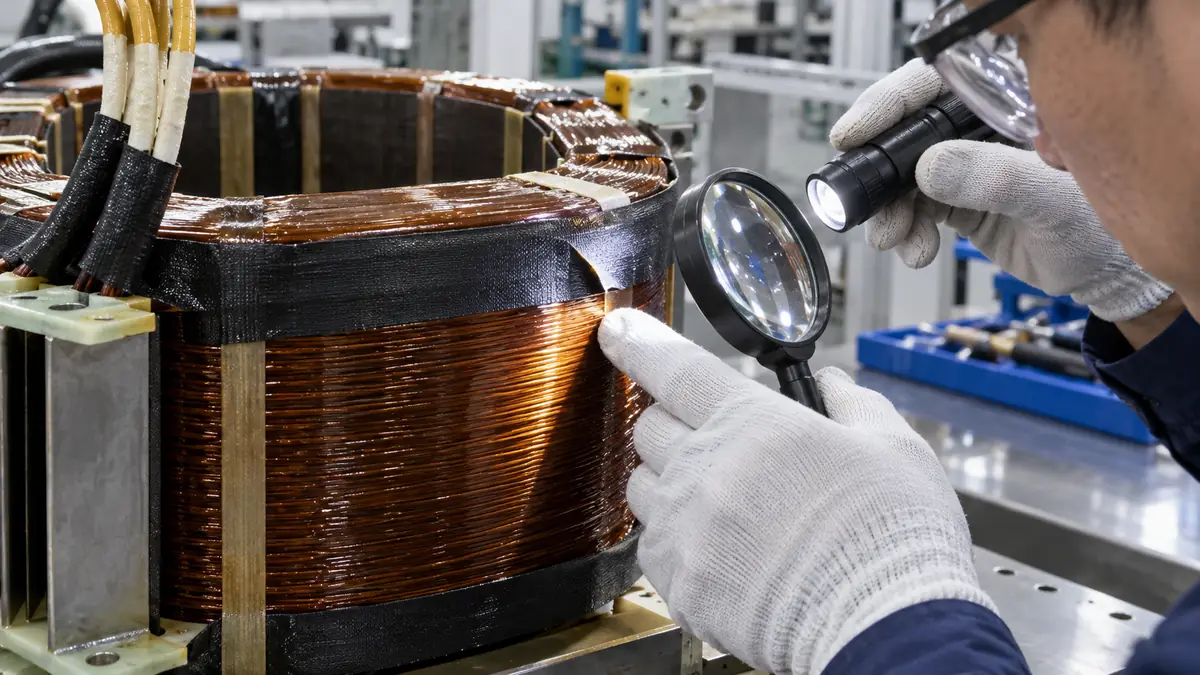
Potential locations include a protected lead transition, a sensor-wire crossing, a small support interface, or a serviceable junction already designed for tape insulation. Direct wrapping of the active work coil requires special caution because geometry, coupling, heat, vibration, and coolant exposure can differ sharply from a bench coupon.
Insulation Options to Compare
| Option | Potential role | Primary design question |
|---|---|---|
| Polyimide film tape | Thin local electrical insulation and wire retention | Does the adhesive remain compatible with heat, field, surface, and service interval? |
| Polyimide film without adhesive | Engineered layer insulation under a separate retention method | How is the film held without gaps or movement? |
| Glass-fiber sleeving or tape | Abrasion-resistant lead and cable insulation | Is the bulk and fiber construction suitable near the coil? |
| Ceramic support or barrier | Rigid high-heat spacing and electrical separation | Can it handle mechanical load and thermal shock? |
| Molded or braided insulation | Protected power-lead routing | Does it meet bend, cooling, and termination requirements? |
Information Needed Before Tape Selection
| Parameter | What to document | Why it matters |
|---|---|---|
| Electrical duty | Voltage, frequency, current path, insulation coordination, and fault strategy | A generic dielectric value does not define system suitability |
| Thermal exposure | Local temperature history, cycle duration, radiant heat, and cooling state | Backing and adhesive see the real local profile |
| Environment | Coolant, humidity, scale, oil, cleaner, dust, and metal debris | Contamination changes adhesion and insulation risk |
| Mechanics | Vibration, bend radius, clamp load, abrasion, and service handling | Thin film can nick or creep at sharp edges |
| Maintenance | Inspection access, replacement interval, lockout procedure, and damage limits | Tape must not conceal developing failures |
Choose the Adhesive Deliberately
Silicone-adhesive polyimide tape is commonly screened for elevated-temperature processing, while acrylic constructions may be considered for other bonding or aging priorities. The label alone is not enough. Request construction-specific data and test the exact surface, exposure time, chemical contact, wrap pressure, and removal requirement.
Control Thickness and Overlap
Film thickness, total tape thickness, and overlap count affect the built-up diameter and local stiffness. Too little overlap can leave a gap; excessive overlap can create a ridge, trap contamination, or interfere with a clamp. Define the starting point, wrap direction, overlap window, termination position, and allowed repair.
Protect Edges and Bend Transitions
Polyimide film is strong for its thickness but can be damaged by burrs, sharp conductor edges, repeated flexing, or tool contact. Deburr and inspect the approved surface without removing material that controls coil geometry. At a moving or highly abrasive point, a sleeve or rigid barrier may be more appropriate.
Safe Installation Workflow
- Apply lockout and verification. Follow the equipment-specific isolation procedure and confirm the system is de-energized, depressurized where required, and cool.
- Confirm the repair scope. Use the released drawing or work instruction; do not improvise tape placement on an active coil area.
- Inspect the component. Check for leaks, cracks, overheating evidence, looseness, burrs, contamination, and damaged supports.
- Prepare the approved surface. Clean with the authorized method and allow it to dry fully.
- Wrap without wrinkles. Maintain the specified tension and overlap, keeping the tape away from prohibited zones.
- Terminate securely. Position the final edge where flow, abrasion, or repeated handling will not lift it.
- Document the work. Record tape construction, lot, location, wrap pattern, date, and inspector.
- Run the approved return-to-service checks. Inspect through representative cycles using the site's electrical and thermal safety procedure.
Failure Modes and Corrective Directions
| Observed issue | Checks | Corrective direction |
|---|---|---|
| Edge lift or unraveling | Contamination, wrap direction, tension, temperature, and coolant contact | Correct the root cause and requalify the termination |
| Discoloration or brittle film | Local heat, radiant exposure, cycle time, and hidden hot spots | Review the thermal design rather than adding more layers |
| Adhesive residue during service | Construction, heat history, chemical contact, and replacement interval | Screen another adhesive or revise maintenance timing |
| Puncture or cut | Burrs, clamp edges, tool contact, vibration, and insufficient mechanical protection | Remove the damage source or use a tougher barrier |
| Moisture beneath the wrap | Coolant leak, condensation, cleaning, and sealed overlap | Repair the leak and prevent tape from hiding the inspection area |
Qualification and Inspection
Use representative coil or lead assemblies, not only flat metal coupons. Reproduce the approved wrap pattern, heat cycles, cooling conditions, vibration, chemical exposure, and maintenance handling. Acceptance criteria may include visual condition, edge position, absence of trapped moisture, insulation checks defined by the equipment engineer, and easy identification of leaks or overheating.
Any change to tape construction, supplier, thickness, adhesive, wrap count, cleaner, or installation location should enter the site's change-control process. Safety-critical electrical decisions belong to qualified engineering personnel.
Related Products and Articles
- Explore the polyimide tape range.
- Review what polyimide tape is and how it is selected.
- Compare formats in the polyimide tape properties and types guide.
- Send the coil duty and insulation drawing for a tape-construction discussion.
Frequently Asked Questions
Can polyimide tape be wrapped directly on an induction heating coil?
Only when the coil or equipment design authority approves the location and the exact construction is qualified. Tape must not obstruct cooling, alter critical geometry, hide leaks, or replace required rigid insulation.
Is Kapton tape the same as polyimide tape?
Kapton is a trade name for a polyimide film. Industrial buyers should identify the complete tape construction, including film, adhesive, thickness, liner, and supplier data, rather than relying on the generic nickname.
How many overlap layers are required?
There is no universal count. The drawing or work instruction should define overlap, tension, start and finish positions, and allowed build-up based on electrical, thermal, and mechanical design.
Can tape stop a coolant leak?
No. A leaking copper tube, fitting, or cooling circuit requires an approved repair. Tape should not hide a leak or be treated as a pressure-containing material.
What information should be included in an RFQ?
Provide the application location, conductor and support materials, electrical duty, thermal history, cooling environment, chemical exposure, wrap geometry, thickness limits, inspection method, quantity, and qualification plan.
Evaluate Polyimide Tape for a Coil Assembly
Share the approved insulation location, electrical and thermal duty, cooling environment, mechanical risks, wrap drawing, and inspection criteria. JIAO TAO TAO can help shortlist a construction for controlled engineering evaluation.
PTFE Tape for Sublimation Heat Press Platen Protection
PTFE Tape for Hot-Melt Adhesive Rollers and Guide Plates
Related Article
Need help choosing the right industrial tape?
Send us your application details, including temperature, surface material, size, quantity and current problem. Our team will help recommend a suitable tape material or custom die-cut solution.

simon@jiaotaotao.com


+86-136 1277 5969


+86-136 1277 5969
