
PET Silicone Tape for Busbar Contact Pad Masking
Application Solutions · Powder-Coated Power Equipment
PET Silicone Tape for Busbar Contact Pad Masking
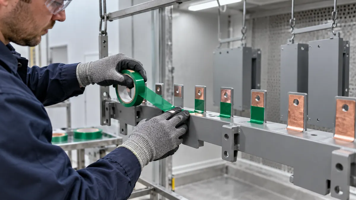
PET silicone tape for busbar contact pad masking can keep a drawing-defined copper or plated contact land free of powder coating while the surrounding bracket or enclosure is finished. Reliable masking requires controlled geometry, clean surfaces, measured thermal exposure, disciplined removal, and electrical verification of the completed assembly—not a generic assumption that every green PET tape fits every busbar.
Quick Answer
Use PET silicone masking tape only on the exact busbar area identified by the released drawing and finishing plan. The tape may protect a bolted contact pad, a grounding land, a test point, or a joining surface, but it does not define the electrical design. The product owner must decide which copper, plating, or treated metal stays exposed and how the completed joint will be accepted.
Define the Contact Boundary Before Masking
A busbar connection may depend on pad dimensions, flatness, surface finish, plating, hardware stack, joint compound, torque, and corrosion controls. Masking should preserve that released interface without exposing unnecessary metal beside it. An oversized bare zone can change corrosion protection and appearance; an undersized zone can leave powder beneath a terminal, washer, sensor, or connector.
Use a dimensioned mask drawing tied to stable datums. Do not locate the tape from a coating color break or operator estimate. Include clearance around holes, edge radii, slots, welds, bends, stand-offs, and any area where the mask must not interfere with racking or grounding.
| Boundary input | What to define | Why it matters |
|---|---|---|
| Contact function | Power joint, ground, test point, sensor, or assembly land | Sets the cleanliness and verification plan |
| Pad geometry | Length, width, radii, holes, tolerance, and datum | Controls the tape or die-cut drawing |
| Surface | Copper, plating, treatment, roughness, and contamination limits | Changes adhesion and residue risk |
| Coating stack | Pretreatment, dry-off, powder, cure, repeat passes, and cooling | Defines the real thermal and chemical exposure |
| Joint acceptance | Fit, torque, resistance, temperature rise, and corrosion checks as applicable | Connects masking to final function |
Select the PET Silicone Tape Construction
PET backing and edge control
PET film provides a thin, dimensionally stable masking face for many finishing operations. Backing thickness affects handling, puncture resistance, corner conformity, and the step created at the coating edge. A thicker film can be easier to position but may resist tight bends; a thinner film can follow gentle geometry but may be easier to wrinkle or nick.
Silicone adhesive and surface condition
The silicone pressure-sensitive adhesive must wet out the actual copper or plated surface, remain seated through handling and heat, and remove within the approved window. Oil, oxidation, fingerprints, polishing residue, rinse residue, and moisture can create edge channels or inconsistent peel. Define when masking occurs relative to cleaning and pretreatment, and approve the exact tape code rather than color alone.
Thermal history and removal
Record dry-off, cure, line stops, repeated passes, cooling, and the longest permitted delay before removal. A thick copper bar can heat and cool differently from the surrounding sheet metal. Evaluate the tape at the adhesive location on representative assemblies instead of converting a catalog maximum into a process approval.
Compare Mask Formats
| Mask format | Best fit | Main control point |
|---|---|---|
| Slit PET tape | Long rectangular pads, prototypes, and changing sizes | End joints, overlap, straightness, and placement variation |
| Kiss-cut rectangle | Repeated pad geometry and faster placement | Die-cut tolerance, liner release, and orientation |
| Frame or ring | Contact area surrounding a hole or fastener feature | Inner and outer boundary plus pull-tab location |
| Multi-part carrier | Several pads with fixed spacing on one assembly | Datum accuracy, carrier stability, and piece accountability |
| Combined tape and plug | Contact land plus hole or threaded feature | Gap or bridge between the two mask methods |
A liner-backed die cut can reduce hand trimming near conductive surfaces and add a nonadhesive pull tab. For several pads, a common carrier may improve spacing and confirm that every mask was applied. The best format balances placement repeatability, cycle time, removal access, waste, and traceability.
Recommended Masking Workflow
- Confirm the drawing. Identify the released contact land, holes, keep-outs, and inspection datum.
- Verify materials. Match busbar revision, surface finish, tape code, mask drawing, and powder system.
- Inspect the pad. Stop for burrs, oil, oxide, moisture, loose plating, or surface damage.
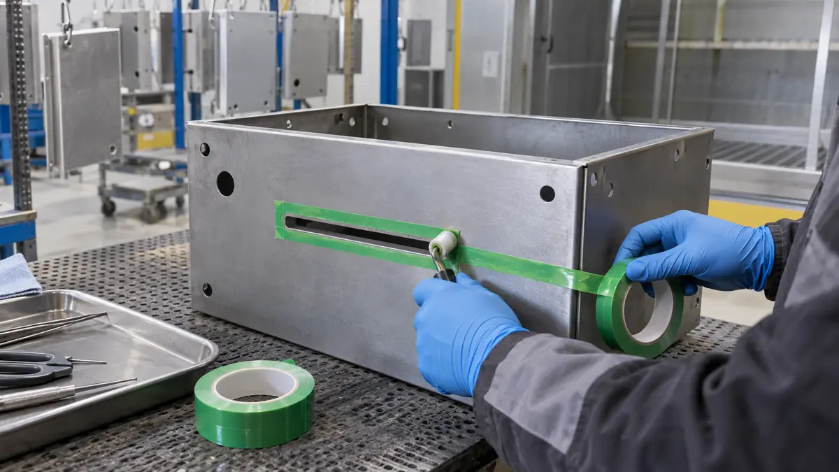
- Apply from the datum. Place the tape or die cut without stretching the PET film or touching the adhesive.
- Burnish the perimeter. Use controlled pressure, especially beside holes, bends, and ends.
- Inspect before spraying. Check coverage, gaps, wrinkles, overlaps, tabs, and piece count.
- Run the qualified cycle. Keep thermal history and line interruptions within the released window.
- Remove by the approved method. Support the part and peel in the validated direction and condition.
- Inspect the exposed pad. Check dimensions, residue, fragments, coating edge, and surface damage.
- Verify the finished joint. Perform the assembly and electrical checks required by the product owner.
Validate the Complete Busbar Assembly
Trials should include representative copper or plating lots, pad geometries, bends, thermal masses, rack positions, operators, powder builds, and maximum approved delays. Flat coupons can screen adhesion and removal, but they do not reproduce a bent busbar, recessed pad, fastener hole, edge burr, or the joint stack.
| Validation group | Observe | Release evidence |
|---|---|---|
| Placement | Pad boundary, hole clearance, alignment, and repeatability | Drawing, gauge, vision check, or approved image standard |
| Process hold | Lift, wrinkles, shrinkage, powder creep, and trapped liquid | Inspection through the complete finishing cycle |
| Removal | Tearing, fragments, residue, staining, and coating-edge damage | Defined removal condition and accepted method |
| Assembly | Hardware seating, flatness, fit, torque procedure, and rework access | Product engineering requirements |
| Electrical result | Resistance, continuity, temperature rise, or other released tests | Assembly-level acceptance criteria |
Troubleshoot Defects Systematically
Powder beneath the mask can result from contamination, weak edge pressure, a nicked die cut, unsupported tape over a hole, or poor joint design. Residue may involve the exact adhesive, surface finish, extended heat, repeated passes, or delayed removal. A jagged boundary can involve stretched film, a burr, excess powder build, or a steep peel direction.
Do not respond automatically by choosing stronger adhesion. Compare the part history, pad finish, placement record, rack position, measured temperature, removal delay, and mask geometry. Change one controlled variable, repeat the relevant qualification, and update the drawing or work instruction only after the final joint passes its required checks.
Related Products and Articles
Frequently Asked Questions
Can PET silicone tape mask a copper busbar during powder coating?
It can be screened for a drawing-defined contact pad when the exact tape, copper or plating finish, pretreatment, measured cure cycle, geometry, and removal method are qualified together.
Should the fastener hole be covered by the same tape?
Only if the released mask drawing and process approve that detail. Some assemblies need a separate plug, disc, or combined mask so the hole and contact land are controlled independently.
Does a clean-looking pad prove a low-resistance joint?
No. Visual cleanliness is one inspection input. The completed joint must meet the product owner’s assembly and electrical acceptance tests.
Is a die-cut mask better than slit tape?
A die cut can improve repeatability, corner shape, liner handling, and piece accountability for stable geometry. Slit tape remains useful for prototypes and frequently changing sizes.
What should a busbar mask RFQ include?
Provide the drawing, pad tolerance, busbar material and finish, pretreatment, powder and measured thermal profile, format, quantity, removal condition, and final joint checks.
Build a Controlled Busbar Masking Trial
Share the busbar and contact-pad drawing, surface finish, coating stack, measured thermal history, placement datum, required mask format, removal window, annual quantity, and joint acceptance plan. JIAO TAO TAO can prepare slit or die-cut PET silicone tape samples for production evaluation.
Discuss PET busbar contact-pad masking
Polyimide Tape for Ceramic Heater Thermistor Lead Fixation
Related Article
Need help choosing the right industrial tape?
Send us your application details, including temperature, surface material, size, quantity and current problem. Our team will help recommend a suitable tape material or custom die-cut solution.

simon@jiaotaotao.com


+86-136 1277 5969


+86-136 1277 5969
