
Copper Tape Overlap Conductivity: What a Seam Test Shows
Copper tape overlap conductivity depends on the complete connection: the foil, the adhesive between layers, and contact at the seam. Conductive copper alone does not prove that current will cross an overlap. A direct-current continuity check can help identify an open or unstable joint, but it cannot establish shielding effectiveness or a fault-current rating.
For engineers and production buyers joining foil strips on an enclosure or component, the useful question is where the intended current must travel. Define that path before selecting a tape or judging a meter reading.
1. Separate the foil path from the adhesive interface
Along an unbroken strip, current can travel through the copper foil. Across a lap joint, it must also pass from the lower strip into the adhesive on the upper strip, then into its foil. The copper-to-adhesive interfaces matter as well as the bulk adhesive formulation.
A conductive adhesive is selected to provide an electrical path through that bond line. An ordinary non-conductive adhesive may hold two copper strips together without providing the required through-thickness connection. A protective coating, paint, liner fragment or contamination can interrupt an otherwise suitable arrangement.
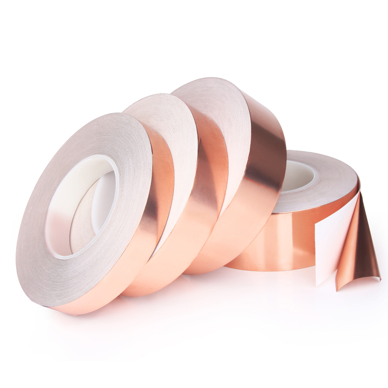
The JIAOTAOTAO conductive copper tape page identifies a copper-foil and conductive-acrylic construction. Confirm the exact offered grade and its electrical test information; do not assume every copper tape in a catalogue has that same adhesive.
2. Compare the actual overlap construction
| Connection | What needs checking | Misleading shortcut |
|---|---|---|
| Probe to probe on one foil strip | Foil continuity and probe contact | Calling this a through-adhesive test |
| One foil strip overlapped onto another | Adhesive type, bonded area and seam contact | Assuming visible coverage proves continuity |
| Foil bonded onto a metal panel | Panel finish and the complete bonded interface | Treating painted metal as exposed metal |
| Foil crossing a corner or opening | Wrinkles, bridging and continuity along the intended route | Checking only the flat centre of the strip |
State which connection the drawing requires. A sample that passes one arrangement does not automatically qualify another.
3. Build a repeatable seam trial
Use a disconnected sample assembly and the same surface finish intended for production. Agree the acceptance method before testing; there is no universal overlap width or resistance limit for every tape and application.
- Record the construction. Identify the foil, adhesive, surface coating, liner and lot supplied.
- Prepare the surface. Remove oil, loose residue and moisture using a procedure compatible with the finish. Record any oxide or protective coating rather than silently changing the specimen.
- Control the joint. Record overlap dimensions, alignment and application pressure or rolling procedure. Avoid trapped air, folded edges and stretched foil.
- Keep conditions comparable. Use the same dwell, temperature and probe positions for the comparison. Mark the test points so another operator can repeat it.
- Check the assembled state. Inspect after the handling or environmental exposure defined for the application. A reading taken while the joint is temporarily clamped may describe the clamp, not the final assembly.
4. Investigate a high or changing reading
Start with the measurement setup before replacing the tape. Probe contact and leads can contribute to a low-resistance measurement. Excessive probe force can also change the seam being investigated.
| Observation | Possible issue to inspect | Useful comparison |
|---|---|---|
| One strip reads consistently; the overlap does not | Wrong adhesive or poor contact at the lap | Same foil with a documented conductive-adhesive construction |
| Reading changes when the probe moves | Surface film, variable probe contact or a damaged strip | Repeat at marked points with controlled contact |
| Reading improves only under squeezing | Incomplete contact, wrinkles or a pressure-dependent interface | Measure again in the intended unassisted installed state |
| Initial result changes after storage | Surface condition, joint movement or environmental exposure | Document the change and compare retained samples |
5. Know what a continuity result leaves unanswered
A continuity beep is a screening result, not a precise contact-resistance value. When lead resistance is significant relative to the joint, a suitable four-wire measurement can reduce lead-related error. Specify the fixture, current, voltage measurement points and specimen condition with the result.
A direct-current test does not measure how an enclosure attenuates electromagnetic interference at its operating frequencies. Openings, seam geometry, contact distribution and other parts of the assembly still affect that outcome. Evaluate shielding with a method appropriate to the complete design.
Likewise, a low reading does not establish safe current capacity, temperature rise or protective bonding performance. Keep those design requirements separate from the assembly continuity check.
6. Specify the connection before requesting tape
Use the copper tape range as a starting point, then send JIAOTAOTAO a sketch of the overlap, substrate and finish, electrical purpose, expected environment, tape dimensions and order quantity. Include the agreed test method or acceptance requirement, rather than asking only for a conductive tape.
Request a construction review and sample quotation with photographs of the joint and any unstable readings. This gives the discussion a defined connection to evaluate.
7. Frequently asked questions
Does overlapping copper tape automatically make an electrical connection?
No. The overlap places one adhesive layer against another strip of foil. Current must cross that interface. Confirm that the selected adhesive is electrically conductive and evaluate the completed overlap on the actual surface, rather than relying on the copper colour or a product-family name.
Will pressing harder make non-conductive adhesive conductive?
Pressure helps establish contact for a suitable pressure-sensitive construction, but it does not change an insulating adhesive into a specified conductive adhesive. A reading obtained only while pressing a probe or squeezing the seam needs investigation, not a stronger installation-pressure claim.
Does a continuity beep prove that an enclosure is shielded?
No. It indicates a direct-current path under that meter's conditions. Shielding also depends on the enclosure, openings, joints, frequency and installation. A seam continuity check can support assembly control, but it cannot replace evaluation of the complete shielding design.
Can copper tape replace a protective grounding conductor?
Do not select adhesive foil tape for protective bonding or fault-current duty from a continuity reading. Those functions require a separately engineered and qualified connection. State the intended electrical role when requesting a sample so it is not confused with a shielding seam or signal-level contact.
Microprismatic vs Glass Bead Reflective Tape: Selection Guide
Anti Slip Tape Peeling on Concrete: What to Check First
Related Article

Need help choosing the right industrial tape?
Send us your application details, including temperature, surface material, size, quantity and current problem. Our team will help recommend a suitable tape material or custom die-cut solution.

simon@jiaotaotao.com


+86-136 1277 5969


+86-136 1277 5969
