
PET Silicone Tape for Battery Tab Welding Protection
PET Silicone Tape for Battery Tab Welding Protection
PET silicone tape for battery tab welding protection is used around, not across, the intended metal-to-metal weld interface. It can temporarily mask adjacent cell surfaces, organize local insulation, and reduce accidental contact during fixture loading. The tape must be selected against the real cell format, welding process, cleaning method, heat path, removal step, and electrical-clearance requirement.

Key Takeaways
- Keep adhesive, film, and contamination outside the specified weld footprint.
- Measure the temperature at the tape location; do not substitute weld-energy settings for tape temperature.
- Evaluate PET film, silicone adhesive, thickness, color, cut geometry, and removal method as one system.
- Approve the tape on production-representative cells and fixtures with electrical, mechanical, and visual checks.
What PET Silicone Tape Does Near Battery Tab Welding
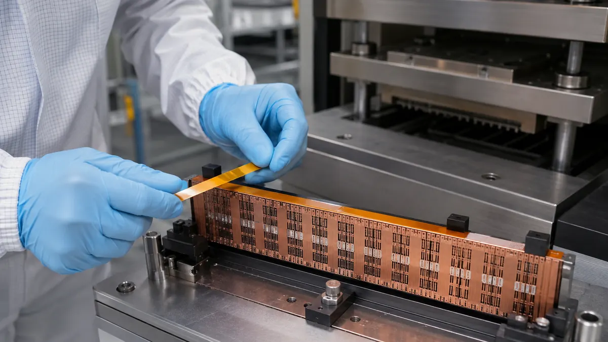
Battery tab joining can use resistance, laser, ultrasonic, or another qualified welding process. Each method concentrates energy differently. A narrow PET silicone tape mask may be considered outside the weld zone to protect a pouch edge, separate neighboring conductive features, identify a process boundary, or hold a temporary insulating layer during handling.
The tape is not a substitute for the cell maker’s approved insulation stack, weld fixture, spacing, overcurrent protection, or finished-pack validation. It should never be placed between surfaces that must form the weld. Any tape left in the assembly must be reviewed as a permanent material; any tape removed after welding needs a defined peel direction and inspection step.
Temporary Masking, Process Aid, or Permanent Insulation?
| Use mode | Possible purpose | Primary approval question |
|---|---|---|
| Temporary adjacent mask | Protect a nearby film, pouch edge, busbar surface, or fixture contact area | Can it be removed without residue, tearing, or disturbing the tab? |
| Temporary handling aid | Hold an insulating sheet or organize a tab before fixture closure | Does it stay clear of the weld and release at the planned step? |
| Visual process boundary | Make a keep-out area easier for operators or vision inspection to recognize | Is color controlled and detectable under actual lighting? |
| Permanent local insulation | Remain near the tab after joining as part of the approved stack | Has the complete electrical, thermal, chemical, and aging design been validated? |
| Fixture protection | Cover a non-contact fixture surface exposed to incidental debris | Does the tape change grounding, heat flow, clamping force, or dimensional accuracy? |
Selection Data for a Battery Tab-Welding Tape
| Parameter | Record it as | Why it matters |
|---|---|---|
| Cell and tab construction | Pouch, prismatic, or cylindrical cell; tab metal, plating, width, and thickness | Defines geometry, conductive surfaces, and handling risk |
| Welding process | Resistance, laser, ultrasonic, or approved alternative; energy and clamp sequence | Changes the local heat, vibration, plume, and pressure environment |
| Tape keep-out zone | Distance from weld footprint, sensor, clamp, and electrical contact in mm | Prevents the process aid from entering a functional interface |
| Measured exposure | Temperature at the tape location and duration, including repeated cycles | Provides the condition used to screen backing and adhesive |
| Bonding surface | Cell film, coated metal, bare metal, insulation sheet, or fixture finish | Controls wet-out, residue risk, and removal behavior |
| Tape construction | PET thickness, total thickness, silicone adhesive, width, color, and liner | Controls stiffness, edge profile, visibility, and application repeatability |
| End condition | Removed after welding or retained in the finished assembly | Determines the necessary qualification scope |
How to Choose the Tape Construction
Confirm the real temperature at the adhesive line
Weld settings, electrode temperature, laser power, and tab temperature are not the same as the temperature experienced by the tape. Place measurement points at representative tape locations during a controlled engineering trial. Include the hottest credible position, multiple cycles, fixture heat soak, and the planned cooling time before removal.
Keep total thickness inside the fixture budget
A thin PET backing can provide dimensional stability, but the complete tape adds thickness under clamps, covers, or inspection features. Check the total construction, overlaps, folded edges, and liner remnants. A tape that interferes with fixture closure can change tab position or clamping force.
Use color as an inspection aid, not a grade
Blue, green, transparent, and other PET film colors can help an operator or camera confirm presence and removal. Color does not establish heat resistance or electrical performance. Control the supplier, construction code, width, thickness, adhesive, and revision independently of the color.
Decide whether slit rolls or die-cut pieces are safer
Slit tape is flexible for development work, while a die-cut piece can define the keep-out boundary, tab opening, pull tab, and placement datum. For high-volume assembly, a kiss-cut part on a stable liner can reduce hand trimming near live or delicate cell features.
Recommended Application Workflow
- Work to the approved cell-handling procedure. Confirm isolation, state-of-charge controls, ESD requirements, and damaged-cell response before setup.
- Identify the weld footprint and keep-out boundary. Use the released drawing or fixture datum rather than estimating by eye.
- Inspect the bonding surface. Reject contamination, electrolyte evidence, burrs, folds, oxide, or damage according to the process plan.
- Apply the tape without stretching. Align from a stable datum and press only on the intended non-weld surface.
- Inspect the exposed metal interface. Confirm that no film, adhesive edge, loose liner, fiber, or fingerprint enters the weld area.
- Load and close the fixture. Verify that tape thickness does not alter tab alignment, clamp seating, or sensor readings.
- Run the qualified weld cycle. Monitor the defined process variables and stop on any abnormal condition.
- Remove or retain as specified. If temporary, peel in the validated direction and inspect residue; if permanent, verify final coverage and clearance.
Qualification and Failure-Mode Checks
| Observed issue | Tape checks | Process checks |
|---|---|---|
| Tape edge enters the weld | Die-cut geometry, width tolerance, liner release, stretch during application | Placement datum, fixture clearance, operator access, vision threshold |
| Residue after removal | Adhesive compatibility, exposure history, storage, peel angle | Measured local temperature, dwell, contamination, cooling time |
| Film shrinks or curls | PET grade, backing thickness, cut orientation, overlap | Heat path, repeated cycles, distance from weld, fixture heat soak |
| Tab position changes | Total thickness, folded edge, trapped air, part tolerance | Clamp seating, fixture wear, loading sequence, dimensional stack |
| Inspection misses the tape | Color contrast, transparency, gloss, edge definition | Camera angle, lighting, background, software threshold, obstruction |
Approval should include weld quality according to the released process, electrical isolation where applicable, visual inspection, removal behavior, residue review, dimensional checks, and any required aging sequence. Record the tape lot, cell lot, fixture revision, placement method, measured exposure, weld settings, and failure mode. Supplier typical data is a screening input, not a guarantee for a battery assembly.
Related Products and Articles
- Review the polyester silicone tape range for PET film masking and insulation constructions.
- Compare broader construction factors in the PET high-temperature tape technical guide.
- For higher-temperature battery insulation designs, see polyimide tape for lithium battery insulation.
- Send the cell, tab, fixture, and exposure requirements for material-format review.
Frequently Asked Questions
Can PET silicone tape cover the battery tab during welding?
It should not cover surfaces that must form the weld. Use tape only in the approved adjacent area, and define a keep-out zone on the released drawing or fixture plan.
Is blue PET tape automatically suitable for battery welding?
No. Blue is a visibility choice, not a performance rating. Verify the PET backing, silicone adhesive, total thickness, local temperature, surface compatibility, and end-use requirement.
Should the tape be removed after tab welding?
That depends on its defined role. A temporary mask requires a controlled removal and residue inspection step. Tape retained as insulation becomes part of the finished assembly and needs the corresponding electrical, thermal, chemical, and aging qualification.
How close can the tape be placed to the weld?
Set the distance through process engineering and validation. Consider the weld footprint, heat-affected area, plume or debris path, fixture geometry, tab movement, and inspection tolerance rather than copying a generic spacing.
Are die-cut tape parts better than slit rolls?
Die cuts can improve repeatability by controlling openings, rounded corners, pull tabs, and placement datums. Slit rolls may be practical for trials or variable geometry. Compare labor, tolerance, contamination control, and removal method.
Prepare a Battery Tab-Welding Tape Trial
Share the cell format, tab metal and dimensions, weld process, drawing, tape keep-out zone, measured local exposure, fixture stack, removal plan, and acceptance criteria. JIAO TAO TAO can help shortlist a PET silicone tape width or converted shape for your own qualification.
Contact the technical team with your battery assembly requirements.
Polyimide Tape for Flexible Heater Insulation and Lead Protection
Acetate Cloth Tape for Motor End-Winding Binding
Related Article
Need help choosing the right industrial tape?
Send us your application details, including temperature, surface material, size, quantity and current problem. Our team will help recommend a suitable tape material or custom die-cut solution.

simon@jiaotaotao.com


+86-136 1277 5969


+86-136 1277 5969
