
PTFE Tape for Thermoforming Heater Plate Release Surfaces
Technical Insights · Plastics Processing
PTFE Tape for Thermoforming Heater Plate Release Surfaces
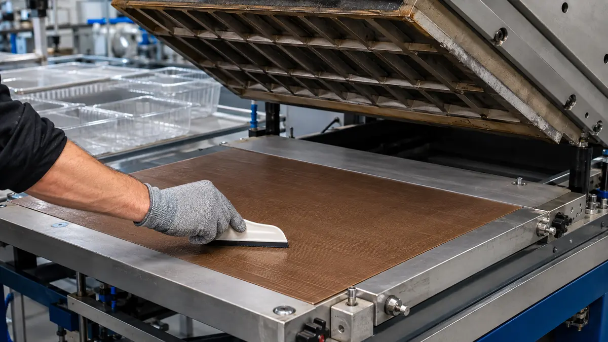
PTFE tape for thermoforming heater plate release surfaces can provide a replaceable low-stick layer on an approved stationary machine area. The construction, seam layout, surface texture, installation method, and maintenance interval must be qualified without altering heating, airflow, guarding, or formed-part quality.
Quick Answer
Adhesive-backed PTFE film or PTFE-coated fiberglass tape may be screened as a replaceable release layer on a thermoforming heater plate, shield, or adjacent stationary surface only where the machine manufacturer and process owner permit it. Tape cannot repair a warped plate, failed heater, damaged sensor, blocked vacuum or airflow path, exposed conductor, worn guide, or incorrect forming recipe.
Define What the PTFE Layer Must Do
A thermoforming line heats a polymer sheet before forming it against or over tooling. Depending on machine design, stationary plates or shields may collect softened polymer, dust, additive bloom, overspray from approved process aids, or adhesive contamination from upstream handling. A smooth replaceable PTFE face can simplify cleanup or reduce sticking at a specifically approved location.
Do not assume every brown sheet in a heating station serves the same function. A heater cover, heat shield, platen face, transport surface, insulation barrier, and forming-tool release sheet have different thermal, mechanical, and electrical requirements. Identify the machine component and its permitted covering before selecting tape.
| Machine area | Possible tape role | Do not overlook |
|---|---|---|
| Stationary heater plate face | Replaceable low-stick surface where approved | Temperature uniformity, sensor location, and surface flatness |
| Adjacent metal shield | Limit light buildup outside the heating zone | Airflow, radiant heat, fasteners, and cleaning access |
| Guide near heated sheet | Reduce drag or pickup on a fixed contact point | Web tracking, clearance, leading edge, and wear |
| Forming tool | Application-specific release aid only if permitted | Vents, texture, dimensions, cooling, and part finish |
| Heater element or live electrical area | Not a general tape-cover location | Use only the machine maker’s approved component system |
Choose the PTFE Tape Construction
PTFE film versus coated fiberglass
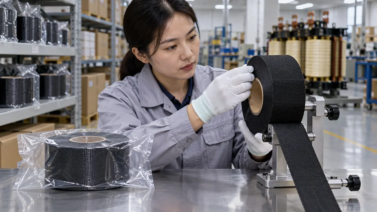
Unsupported PTFE film tape can provide a thin, smooth release face and low edge profile. PTFE-coated fiberglass tape adds woven reinforcement and may suit broader surfaces or repeated maintenance handling, but its weave and coating finish can influence texture transfer or contact marks. These constructions are not interchangeable, and neither is plumbing thread-seal tape.
Adhesive and release liner
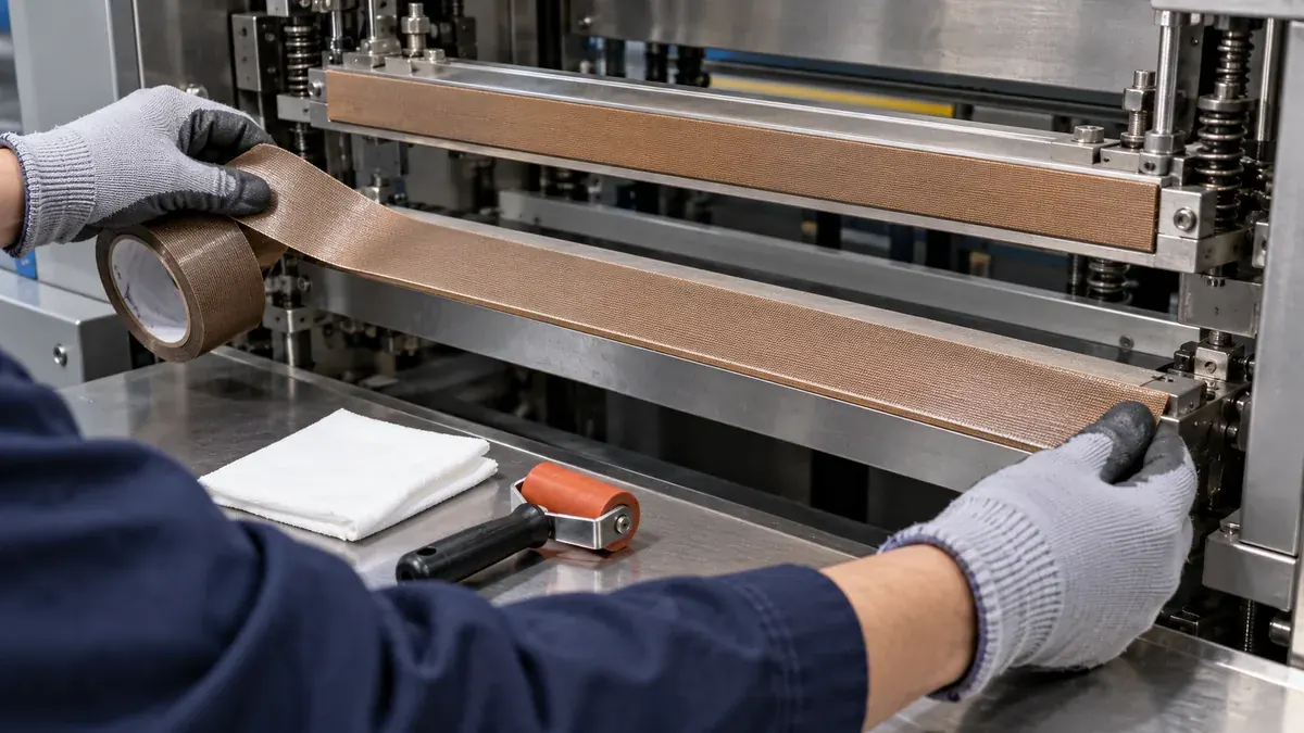
The pressure-sensitive adhesive must hold on the approved metal surface through the qualified thermal cycle yet support controlled replacement. Record adhesive family, total thickness, liner type, storage condition, roll width, and lot. A liner protects the adhesive before installation and can help position large sheets without premature contact.
Temperature, pressure, and cleaning
Measure the real temperature at the tape location across startup, steady production, pauses, and shutdown. Include pressure or sheet contact, cycle rate, cleaning agents, polymer type, and any process additive. Approve the complete construction from representative trials rather than a generic temperature number.
| Selection input | Record for evaluation | Potential effect |
|---|---|---|
| Release face | PTFE film or coated fiberglass, finish, weave, and defects | Release, marking, cleaning, and wear |
| Bonding layer | Adhesive, thickness, liner, peel, and heat exposure | Edge hold, bubbles, removal, and residue |
| Machine surface | Metal, finish, flatness, fasteners, ports, and sensors | Contact area and permitted coverage |
| Forming process | Polymer, sheet gauge, recipe, cycle, pressure, and cooling | Thermal demand and part acceptance |
| Maintenance | Cleaner, tool, inspection interval, and replacement method | Surface damage and repeatability |
Design the Surface, Edges, and Seams
Use the widest practical format that can be installed flat and repeatably. Fewer seams can reduce steps and contamination traps, while an overly wide sheet can be difficult to align without bubbles or creases. Keep tape clear of sensors, vacuum holes, air passages, clamps, moving joints, grounding points, guards, and service fasteners unless the approved drawing explicitly includes them.
If more than one piece is required, define butt joint or overlap, direction relative to sheet travel, maximum gap or step, and allowable seam location. Place the leading edge so normal material motion does not peel it. Round exposed corners when the machine design permits, and do not bridge a recess that must remain open.
Recommended Installation Workflow
- Isolate the machine. Apply the released lockout and confirm a safe temperature.
- Identify the exact surface. Match the maintenance drawing and tape part number.
- Remove the old layer. Use the approved direction and tool without gouging metal.
- Inspect the plate. Stop for warping, corrosion, burrs, loose hardware, or heater damage.
- Clean and dry. Use only the approved agent and lint-control method.
- Dry-fit the piece. Confirm dimensions, seam position, ports, sensors, and edges.
- Apply progressively. Peel the liner in stages and press air toward the free edge.
- Finish the seams. Use the approved overlap or butt-joint layout without stretch.
- Inspect before restart. Check flatness, edge contact, clearance, and foreign material.
- Run the release trial. Restore guards and follow the approved startup sequence.
Validate the Complete Thermoforming Process
Compare baseline and taped conditions using representative polymer, sheet thickness, forming recipe, machine speed, production pauses, cleaning, and the longest planned service interval. Monitor the parameters already required by the owner instead of changing setpoints simply to accommodate the tape.
| Check | What to compare | Reason |
|---|---|---|
| Heating behavior | Approved temperature measurements and warm-up stability | Detect unintended insulation or local heat change |
| Sheet handling | Sticking, drag, sag, tracking, and visible contact | Confirm the release layer solves the defined problem |
| Formed parts | Dimensions, wall distribution, finish, marks, and defects | Protect product quality, not just machine cleanliness |
| Tape condition | Bubbles, seams, edge lift, cuts, discoloration, and residue | Set an evidence-based inspection interval |
| Maintenance result | Removal, cleanup time, plate condition, and repeatability | Confirm the total process benefit |
Set Inspection and Replacement Rules
Use condition-based triggers plus a conservative initial inspection interval. Replace the layer when a wrinkle, cut, exposed adhesive, lifted leading edge, open seam, contamination buildup, or surface change could affect the sheet or heat distribution. Do not cover a defect with a second layer unless a released repair instruction explicitly allows it; hidden layers increase thickness and can conceal plate damage.
Record installation date, tape lot, location, installer, machine hours or cycles, inspection findings, removal condition, and part-quality observations. That history is more useful than a universal replacement claim because life depends on geometry, heat, polymer, contamination, cleaning, and operator practice.
↑ Back to contentsRelated Products and Articles
Frequently Asked Questions
Can PTFE tape cover any thermoforming heater?
No. Use it only on a stationary surface approved by the machine manufacturer and process owner. Never improvise a cover over live, moving, sensing, venting, or damaged components.
Is PTFE film tape the same as PTFE-coated fiberglass tape?
No. They differ in reinforcement, thickness, texture, handling, seam profile, and wear. Compare the exact constructions on the approved surface.
Should seams overlap?
Only when the equipment and forming process permit the thickness step. A butt joint avoids an overlap but can open or trap debris, so joint location and direction must be validated.
How often should the tape be replaced?
Base the interval on documented condition, cycles, heat, polymer contact, cleaning, and part results. Replace before defects can influence the process.
What belongs in a PTFE tape RFQ?
Provide machine area, surface dimensions, temperature history, polymer and sheet gauge, contact pressure, cycle rate, cleaner, seam limits, current failure, and acceptance plan.
Build a Controlled Heater-Plate Trial
Share the thermoforming machine and approved surface, measured temperature history, plate dimensions, polymer and sheet gauge, cycle conditions, contamination problem, cleaning method, planned seams, and part-quality checks. JIAO TAO TAO can help shortlist PTFE tape constructions for maintenance evaluation.
Discuss a PTFE release surfacePolyimide Tape for Semiconductor Leadframe Molding Protection
Polyimide Tape for Wave Solder Connector Shielding
Related Article
Need help choosing the right industrial tape?
Send us your application details, including temperature, surface material, size, quantity and current problem. Our team will help recommend a suitable tape material or custom die-cut solution.

simon@jiaotaotao.com


+86-136 1277 5969


+86-136 1277 5969
