
PTFE Tape for Side-Seal Bag-Making Machine Heater Bars
Technical Insights · Flexible-Packaging Equipment
PTFE Tape for Side-Seal Bag-Making Machine Heater Bars
PTFE tape for side-seal bag-making machine heater bars can provide a replaceable low-stick face on an approved stationary sealing surface. Reliable use depends on the exact PTFE construction, heater geometry, film structure, line direction, seam design, temperature history, pressure, cleaning practice, and seal-quality controls.

Quick Answer
Use adhesive-backed PTFE material only on the stationary heater-bar, guide, or shield surfaces approved by the bag-making machine owner. Match the installed tape width and thickness to the released stack, keep leading edges and joints out of critical film travel or seal-pressure zones where the design permits, and confirm seal quality after every material or installation change. Tape cannot correct the wrong temperature, dwell, pressure, web tension, film, alignment, or damaged tooling.
Identify the Exact Side-Seal Machine Zone
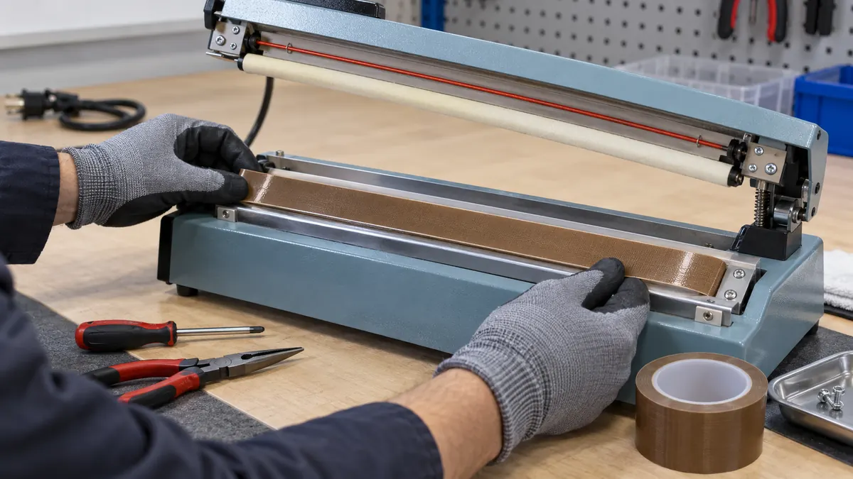
A side-seal bag-making line can unwind film, fold or register the web, apply a longitudinal or side seal, cut the material, collect scrap, and stack finished bags. Depending on the design, the hot interface may be a stationary heater bar, a reciprocating assembly, a knife-and-anvil set, a release strip, or a purpose-built belt. These parts are not interchangeable, and an adhesive PTFE tape intended for one surface should not be moved to another because it appears similar.
Document the original tape route before removal. Record which face is covered, the travel direction, the distance from the seal line, edge clearances, holes or thermocouple keep-outs, the joint position, and whether one or more layers are used. If the existing arrangement is unknown or altered, return to the machine documentation or responsible maintenance authority.
| Machine area | Possible PTFE role | Critical review |
|---|---|---|
| Stationary heater-bar face | Release surface between hot tooling and film | Heat transfer, flatness, pressure, and seal imprint |
| Adjacent guide or shield | Reduce sticking or buildup outside the seal line | Web tracking, leading edge, and clearance |
| Reciprocating or moving assembly | Only as specified by the equipment design | Flex fatigue, edge security, speed, and guarding |
| Replacement belt or sleeve | Purpose-built moving release component | Do not substitute stationary adhesive tape |
| Sensor or vent zone | Normally a keep-out unless explicitly designed otherwise | Temperature feedback, airflow, and control function |
Compare PTFE Tape Constructions
Skived PTFE film tape
Skived PTFE film can offer a smooth, thin release face for selected stationary surfaces. Review puncture resistance, edge curling, dimensional movement, adhesive support, and the permitted thickness. A smooth appearance is useful only if the layer stays flat and the heater stack remains within the machine specification.
PTFE-coated fiberglass tape
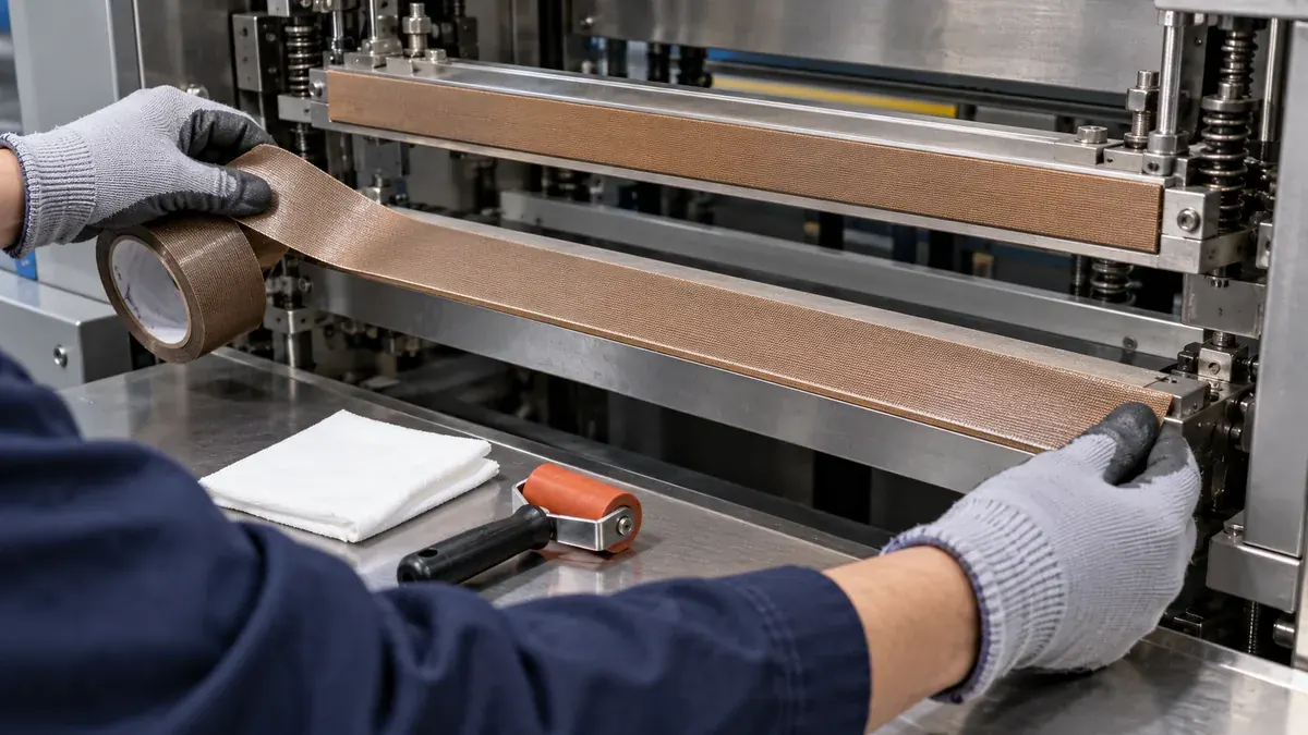
A woven fiberglass reinforcement can improve handling and dimensional strength during installation and repeated thermal exposure. The coated fabric also introduces its own thickness, texture, stiffness, and edge profile. Evaluate whether that surface changes the seal impression or collects material at a cut edge.
Zone tape and converted strips
Zone tape places adhesive only in selected rails, leaving a central PTFE area free to flex or release where the design requires it. Precut strips can include holes, reliefs, tapered edges, and controlled widths. Specify adhesive placement, liner orientation, winding direction, cut quality, and packaging so installers do not reverse the construction.
| Construction | Potential advantage | Main qualification concern |
|---|---|---|
| Skived PTFE film tape | Thin, smooth release face | Puncture, edge curl, adhesive support, and heat transfer |
| PTFE-coated fiberglass tape | Reinforced handling and dimensional stability | Texture, thickness, seam profile, and wear |
| Adhesive-backed zone tape | Adhesive limited to defined support rails | Orientation, free-zone width, and machine compatibility |
| Converted strip or profile | Repeatable holes, width, reliefs, and alignment | Drawing control, liner, tolerance, and cut edge |
| OEM belt or sleeve | Designed moving element for a specific machine | Must not be replaced by a stationary tape format |
Control Edges, Joints, and Travel Direction
An exposed leading edge can catch the web, collect molten polymer, or begin a lift that grows across the heater face. Orient the tape edge and any joint according to the released direction of film travel and the machine design. Avoid hand-cut serrations, adhesive squeeze-out, wrinkles, trapped air, and unsupported tape that bridges a recess.
A butt joint avoids a thickness ridge but can open as materials move. An overlap can cover the base surface but may print through the seal or change pressure. One continuous strip removes an intermediate seam but can be harder to align on a long bar. There is no universal joint rule: select the arrangement through machine-specific trials and place the joint outside the critical seal path whenever permitted.
Controlled Installation and Startup Workflow
- Stop and isolate the machine. Follow the owner's lockout and safe-temperature procedure.
- Record the old installation. Note tape location, width, direction, layers, seams, and relief features.
- Remove the worn layer. Use approved tools without scratching the heater bar or surrounding parts.
- Clean and inspect the base. Check residue, deposits, flatness, burrs, dents, fasteners, and sensors.
- Select the released strip. Match construction, width, thickness, liner, orientation, and lot.
- Apply from a stable datum. Press progressively without stretching or trapping air.
- Finish edges and reliefs. Keep adhesive and tape out of holes, vents, and sensing zones.
- Reassemble safeguards. Restore guards and the original mechanical settings.
- Run controlled startup material. Observe tracking, release, temperature stability, and deposits.
- Release production only after checks. Apply the package owner's seal tests and records.
Validate the Tape With the Film and Seal Process
Use the actual heater bar, machine motion, film structure, printed or coated surfaces, production web tension, line speed, pressure arrangement, temperature profile, cleaning method, and startup sequence. Include credible variation at roll changes, stops, restarts, and the longest approved run. A bench peel test or supplier datasheet cannot reproduce web tracking, thermal cycling, pressure uniformity, and seal inspection.
| Validation group | What to observe | Release question |
|---|---|---|
| Installation | Flatness, wrinkles, trapped air, edge position, seam, and reliefs | Does the tape match the released machine stack? |
| Thermal response | Warm-up, stable running, stops, restarts, and cooldown | Does the process remain inside its approved window? |
| Web handling | Tracking, drag, catches, buildup, and film marks | Does the tape disturb travel or presentation? |
| Seal output | Width, appearance, registration, integrity, and leakage method | Do package-owner acceptance criteria remain satisfied? |
| Maintenance | Wear, cleaning, removal, residue, base damage, and replacement time | Can the condition be inspected and restored consistently? |
Troubleshoot After PTFE Tape Replacement
If film still sticks, inspect whether the correct surface was taped, whether adhesive is exposed, whether the tape is worn or contaminated, and whether the process window or film has changed. An uneven seal can point to trapped air, a wrinkle, overlap ridge, wrong thickness, dirty base, worn heater, or pressure misalignment. A lifting edge can involve poor cleaning, application tension, leading-edge orientation, unsupported geometry, or an unsuitable adhesive.
Do not raise the heater setting simply because a new tape layer changed seal appearance. Additional heat may hide an installation or thickness problem while moving the process outside its qualified window. Restore the released stack, verify instrumentation, and use the product owner's corrective-action plan.
↑ Back to contentsRelated Products and Articles
Frequently Asked Questions
Can PTFE adhesive tape cover any bag-making heater bar?
No. Use it only on a surface and in a format approved by the machine owner. Heater bars, belts, knives, anvils, guides, and sensors can require different components.
Is PTFE film tape the same as PTFE-coated fiberglass tape?
No. They differ in reinforcement, thickness, texture, handling, edge profile, and wear. Compare the exact constructions on the intended machine surface.
Should the tape joint overlap?
Only when the released machine arrangement permits the thickness step. A butt joint avoids a ridge but may open, so joint position, direction, and seal impact must be validated.
How often should heater-bar PTFE tape be replaced?
Use condition criteria such as cuts, glazing, blisters, edge lift, buildup, exposed adhesive, seam movement, or seal changes. Calendar time alone is not a universal replacement rule.
What information belongs in a PTFE tape RFQ?
Provide the machine model or drawing, approved tape location, dimensions, temperature history, motion, line speed, pressure, film structure, cleaning method, current failure, and acceptance tests.
Build a Controlled Heater-Bar Tape Trial
Share the side-seal machine and approved surface, heater-bar drawing, measured temperature profile, film structure, web direction, speed, pressure arrangement, seam limits, cleaning method, observed wear, and package-quality checks. JIAO TAO TAO can help shortlist PTFE film, coated-fiberglass, or converted-strip formats for evaluation.
Discuss side-seal heater-bar tapePolyimide Tape for Composite Cure Thermocouple Lead Routing
Polyimide Tape for Semiconductor Leadframe Molding Protection
Related Article
Need help choosing the right industrial tape?
Send us your application details, including temperature, surface material, size, quantity and current problem. Our team will help recommend a suitable tape material or custom die-cut solution.

simon@jiaotaotao.com


+86-136 1277 5969


+86-136 1277 5969
