
PTFE Film Tape for Low-Friction Chutes and Guide Rails
Technical Insights · Machine Surfaces
PTFE Film Tape for Low-Friction Chutes and Guide Rails
PTFE film tape for low-friction chutes and guide rails creates a smooth replaceable surface where films, labels, coated webs, lightweight parts, or adhesive-backed materials slide across machine hardware. The tape must be matched to the contact load, edge direction, speed, temperature, contamination controls, wear pattern, and maintenance interval.

Quick Answer
A pressure-sensitive PTFE film tape can cover a straight rail, chute lip, plate, or guide where the existing metal surface creates drag or collects light adhesive contamination. It is most useful when a thin, smooth, replaceable lining is preferable to modifying the machine part. It is not structural repair tape, a substitute for worn bearings, or proof that a machine can run outside its released settings.
Where PTFE Tape Fits on Chutes and Guide Rails
Low-friction tape is used on fixed machine surfaces that contact moving material. Examples include the entry lip of a shallow transfer chute, a web guide plate, a rail beside adhesive labels, a cover over a wear-prone slide, or a flat plate where film must move without sticking. The correct placement should support—not redirect—the designed material path.
Installations near heated zones require the measured temperature at the tape and the real cleaning chemistry. Installations near sensors, vacuum ports, nip points, grounded guides, or optical inspection need additional review so the tape does not block a function or change the electrical and dimensional design.
| Surface location | Potential tape role | Do not overlook |
|---|---|---|
| Chute entry lip | Reduce catching at a transition | Leading-edge orientation and impact load |
| Web guide plate | Provide a smooth non-stick contact surface | Web tension, edge tracking, and wrinkles |
| Adhesive-label rail | Reduce light adhesive buildup and drag | Cleaning frequency and contamination transfer |
| Sliding cover plate | Create a thin replaceable wear surface | Clearance and total tape thickness |
| Curved guide | Improve release on a broad radius | Conformability, lifting stress, and seam location |
PTFE Film Tape or PTFE-Coated Fiberglass Tape?
Pure PTFE film tape
PTFE film tape offers a smooth surface and thin profile. It is often screened when the contact material is delicate, the rail is flat, or seams and fiberglass texture could mark the moving web. Film can conform to gentle geometry, but unsupported edges and concentrated abrasion may shorten life.
PTFE-coated fiberglass tape
Reinforced cloth constructions provide greater dimensional stability and tear resistance for many industrial surfaces. The woven structure and coating thickness can create more texture than a pure film. Compare the exact surface finish, tensile behavior, edge durability, and permitted mark on the processed material.
Adhesive and liner
Silicone pressure-sensitive adhesive is common on industrial PTFE tapes, but its bond depends on stainless steel finish, aluminum, coating, prior cleaners, oils, and temperature. A release liner can protect the adhesive and simplify cut parts or wider sheets. Record the approved cleaner and drying time in the maintenance instruction.
| Selection input | Film tape direction | Reinforced cloth direction |
|---|---|---|
| Required surface | Very smooth, thin lining | More robust woven support |
| Contact load | Light, distributed sliding contact | Higher handling or edge stress, subject to testing |
| Geometry | Flat or gentle radii | Flat plates and durable straight covers |
| Wear signature | Fine scratches, edge nicking, or film thinning | Coating wear, exposed weave, or edge fray |
| Processed material | Check for marking, drag, and contamination | Check texture transfer and seam interaction |
Surface Preparation, Edges, and Seams
The machine surface should be sound, smooth, dry, and free of loose coating, burrs, adhesive islands, and the previous tape's residue. Covering a damaged rail can hide a sharp edge rather than remove the risk. Repair the hardware using the approved maintenance method before applying the new lining.
Orient the leading edge so moving material does not drive directly underneath it. Where multiple pieces are necessary, place butt joints or overlaps outside the highest-contact path. If an overlap is approved, its step should face away from travel. Avoid folding tape around a sharp edge unless the grade and geometry have been qualified for that stress.
Recommended Installation Workflow
- Define the target zone. Mark the fixed contact surface and keep-out features on the maintenance drawing.
- Lock out the equipment. Isolate energy and verify the safe condition using the site's procedure.
- Remove the old lining. Use only approved tools and cleaner; do not gouge the rail.
- Inspect the hardware. Correct burrs, dents, loose coating, and mechanical wear before re-lining.
- Cut the tape cleanly. Use the specified width, length, corner radius, and seam plan.
- Position without stretch. Align the tape with the material path and keep edges outside sensors and gaps.
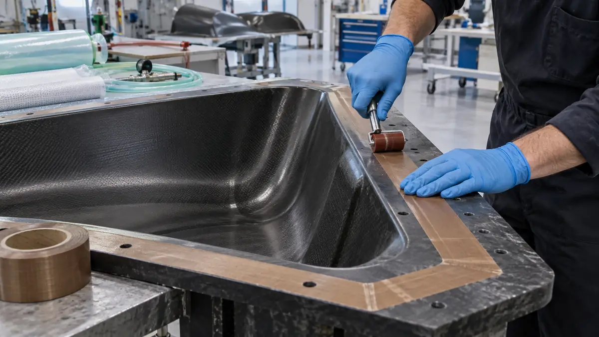
- Apply controlled pressure. Roll from the center outward to exclude air and set the adhesive.
- Trim only as approved. Keep blades away from critical machine surfaces and wiring.
- Inspect before release. Confirm adhesion, edge direction, clearance, and full removal of scrap and liner.
- Run a controlled trial. Observe tracking, drag, marks, noise, debris, and temperature before normal production.
Inspection, Replacement Interval, and Validation
Set a replacement rule from observed wear rather than waiting for the tape to detach. Inspection frequency depends on speed, contact pressure, abrasive particles, adhesive exposure, cleaning, temperature, and start-stop impacts. Keep the first trials short enough to identify an unsafe wear mode before it becomes a production failure.
- Check every leading edge, seam, corner, and radius for lift.
- Look for scratches, punctures, thinning, exposed reinforcement, and embedded debris.
- Compare material tracking, surface marks, and transfer force with the approved baseline.
- Confirm that cleaning does not swell the adhesive or attack adjacent machine finishes.
- Record tape grade, lot, installation date, rail location, runtime, and removal condition.
- Review static-control requirements separately where sensitive webs or electronics are involved.
Troubleshooting Low-Friction Linings
| Observed problem | Likely checks | Corrective direction |
|---|---|---|
| Leading edge lifts | Travel direction, cleaning, radius, impact, and dwell before startup | Relocate or redesign the edge and revalidate adhesion |
| Material catches at a seam | Overlap direction, seam height, alignment, and tension | Move the seam outside contact or use a single wider piece |
| Tape wrinkles during use | Stretch at installation, temperature, width, and substrate flatness | Apply without tension and screen a more stable construction |
| Adhesive contaminates the path | Edge exposure, heat, cleaner, wear, and tape compatibility | Change geometry or construction; shorten inspection interval |
| Processed material is marked | Surface texture, trapped debris, exposed weave, and contact load | Use a smoother film grade and improve cleaning controls |
| Friction remains high | Mechanical alignment, web tension, bearings, rail damage, and root cause | Correct the machine problem instead of adding more tape |
Related Products and Articles
Frequently Asked Questions
Is this the same as plumbing thread-seal tape?
No. This application uses industrial pressure-sensitive PTFE film or PTFE-coated fiberglass tape with an adhesive backing, not unsintered thread-seal tape.
Can PTFE tape repair a damaged guide rail?
No. Burrs, dents, loose coating, misalignment, and worn geometry require the approved mechanical repair. Tape can provide a replaceable contact surface only after the hardware is acceptable.
Is film always better than fiberglass tape?
No. Film offers a smooth thin surface, while reinforced cloth may provide greater handling and tear resistance. Select by load, finish, geometry, wear, and the material being processed.
Should PTFE tape strips overlap?
Only when the approved design allows a step. Prefer a single piece when practical. Any overlap should face away from travel and remain outside the critical contact path.
What should a PTFE guide-rail tape RFQ include?
Provide the machine surface drawing, substrate, contact material, speed, load, temperature, cleaning chemistry, desired finish, tape dimensions, seam plan, wear issue, annual use, and validation criteria.
Define the Surface Before Choosing the Tape
Share the chute or rail drawing, contact material, speed, load, temperature, cleaner, current wear pattern, available thickness, and replacement method. JIAO TAO TAO can help shortlist a PTFE film or reinforced tape for a controlled machine trial.
Discuss a low-friction liningPolyimide Tape for Hall Sensor Lead Protection in BLDC Motors
Polyimide Tape for Hot-Bar Soldering FPC Alignment
Related Article

Need help choosing the right industrial tape?
Send us your application details, including temperature, surface material, size, quantity and current problem. Our team will help recommend a suitable tape material or custom die-cut solution.

simon@jiaotaotao.com


+86-136 1277 5969


+86-136 1277 5969
