
Polyimide Tape for Hot-Bar Soldering FPC Alignment
Technical Insights · Electronics Assembly
Polyimide Tape for Hot-Bar Soldering FPC Alignment
Polyimide tape for hot-bar soldering FPC alignment can temporarily hold a flexible circuit tail, protect a nearby surface, or stabilize an auxiliary fixture area while a controlled heat-and-pressure joint is made. The tape must stay outside the electrical bond interface and be qualified against the real thermode geometry, temperature profile, pressure, flux, removal method, and ESD controls.

Quick Answer
The correct tape does not create the electrical connection. It supports a documented assembly method by holding an FPC in a repeatable position or shielding an approved adjacent area. Joint formation remains the responsibility of the solder, anisotropic conductive film, connector design, thermode, fixture, and validated process window.
Where Polyimide Tape Fits in Hot-Bar Assembly
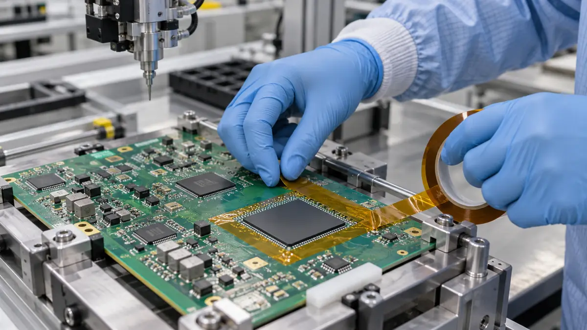
Hot-bar processes use a heated thermode and controlled pressure to join a flexible circuit, cable, or interposer to a PCB, glass, or another circuit. Alignment is critical because narrow conductors must register with matching pads before the thermode descends. A small piece of polyimide tape may hold the flexible tail to a fixture datum or stabilize a section away from the active bond.
Tape can also protect an adjacent surface from incidental contact or help route a tail so it does not spring back during pre-alignment. It should not cover contact pads, enter the intended solder fillet or conductive adhesive zone, fold beneath the thermode, or conceal a joint that must be inspected.
| Possible tape function | Acceptable design question | Do not assume |
|---|---|---|
| Temporary FPC holding | Can a tab maintain registration until the fixture clamps? | That tape alone can control final conductor pitch |
| Tail routing | Does the taped section remain outside the flex zone? | That permanent restraint will not create fatigue |
| Adjacent heat shielding | Is the protected region within the tape's qualified thermal exposure? | That thin film blocks all conducted heat |
| Fixture surface protection | Can the tape be replaced without changing fixture height? | That layer build-up has no effect on pressure |
| Process identification | Can color or tab shape support work instructions? | That appearance proves material identity |
How to Select the Tape Construction
Polyimide film and total caliper
Film thickness affects handling, conformability, stiffness, and puncture resistance. Total tape caliper includes the adhesive and determines the step created beneath a fixture clamp or near the thermode path. Specify both values and measure the completed stack where pressure uniformity matters.
Silicone or acrylic adhesive
Silicone adhesive is commonly screened for short high-temperature masking and clean removal, while acrylic systems may be selected for different holding or aging requirements. These labels do not predict performance by themselves. Evaluate the exact adhesive on the FPC coverlay, solder mask, glass, metal fixture, or other real surface.
Slit width, die-cut tab, and liner
Narrow slit rolls work for simple manual placement. A kiss-cut tab on a liner can improve location, orientation, and glove handling in repetitive production. If the tape must be removed after bonding, a non-bonded finger lift can reduce the chance of pulling on the flexible circuit.
| Selection factor | What to document | Why it matters |
|---|---|---|
| Thermal profile | Thermode set point, measured local tape temperature, dwell, cycles, and cooling | The tape may see a different temperature from the joint |
| Substrates | Coverlay, solder mask, copper finish, glass, fixture coating, and cleaner | Adhesion and residue vary by surface |
| Geometry | Pad pitch, tape edge clearance, clamp area, flex bend, and removal path | A misplaced edge can affect pressure or inspection |
| ESD control | Workstation controls, tape unwind behavior, ionization, and sensitive devices | Standard tape should not be assumed to be ESD-safe |
| Conversion format | Roll, sheet, kiss-cut part, liner side, unwind direction, and packaging | Presentation influences placement repeatability |
Placement and Fixture Controls
Define tape keep-out zones on the assembly drawing or work instruction. The controlled distance should account for the thermode footprint, joint inspection region, solder or adhesive flow, clamp faces, fiducials, and the natural movement of the FPC. A general note such as “apply Kapton tape” is not a measurable placement standard.
Fixture datums should locate the circuit before the tape is pressed. Do not stretch the FPC into position and rely on the tape to hold stored tension. Where camera alignment is used, confirm the tape does not cover fiducials or create glare that disrupts vision inspection.
Recommended Application Workflow
- Verify released materials. Confirm the FPC, PCB, joining material, tape code, fixture, and work-instruction revisions.
- Inspect and prepare. Check the contact areas, coverlay, pads, fixture surface, and tape for damage or contamination. Use only the approved cleaning method.
- Load against datums. Position the PCB and FPC without forcing the tail or creating a sharp bend.
- Align the conductors. Use the specified camera, microscope, tooling marks, or mechanical features.
- Apply the tape tab. Place it within the defined zone, press evenly, and keep the edge outside the thermode and joint-inspection envelope.
- Engage the fixture clamp. Confirm the clamp, rather than the tape alone, controls final position where the process requires it.
- Run the approved hot-bar cycle. Use the validated temperature, pressure, time, and cooling sequence.
- Remove or retain as specified. Peel at the defined angle and stage, supporting the FPC to avoid delamination or conductor damage.
- Inspect the joint and surrounding area. Check alignment, wetting or conductive-film result, residue, coverlay damage, and tail routing.
Qualification and Process Verification
Qualification should use representative parts across expected material and process variation. Include minimum and maximum tape placement, realistic storage age, operator handling, repeated fixture use, and the thermal extremes of the validated hot-bar window. Flat coupon adhesion testing is useful for screening but does not replace assembled-joint evaluation.
- Measure conductor-to-pad alignment before and after tape placement.
- Confirm the tape does not alter fixture height, thermode parallelism, or pressure distribution.
- Inspect electrical and mechanical joint results using the product's approved criteria.
- Check for adhesive residue, coverlay lifting, pad contamination, and damage during tape removal.
- Evaluate ESD risk through the site's controlled method if sensitive devices are present.
- Record the tape lot, placement location, thermode cycle, and inspection result for traceability.
Common Problems and Corrective Directions
| Observed problem | Likely checks | Corrective direction |
|---|---|---|
| FPC shifts before bonding | Datum contact, tape area, application pressure, tail stress, and clamp sequence | Improve fixture location and define a larger approved holding tab |
| Tape edge enters the joint | Tab dimensions, operator visibility, liner presentation, and keep-out marking | Use a keyed die-cut shape or stronger placement datum |
| Residue after the cycle | Adhesive type, actual tape temperature, dwell, surface, and removal timing | Screen another construction and revise the peel stage |
| Coverlay lifts during removal | Peel angle, tape adhesion, dwell, FPC support, and surface preparation | Add a finger lift and support the tail during controlled removal |
| Joint pressure is uneven | Tape thickness under clamps, overlapping tabs, fixture wear, and thermode planarity | Move tape outside the load path and control the stack height |
Related Products and Articles
- Review the polyimide tape range for electronics assembly.
- See a 0.04 mm polyimide tape format for PCB masking.
- Compare roll and converted formats in the custom die-cut polyimide tape guide.
- Send your FPC drawing and hot-bar process details for sample discussion.
Frequently Asked Questions
Can polyimide tape form the electrical hot-bar joint?
No. Standard polyimide pressure-sensitive tape is used for holding, masking, or insulation. Solder, anisotropic conductive film, or another specified joining material forms the electrical connection.
Can the tape sit under the thermode?
Only if a released process specifically uses a qualified interposer or protective construction there. A general alignment tab should remain outside the thermode footprint and bond line.
Is silicone adhesive always the best choice?
No. Silicone systems are common for short high-temperature exposure, but residue, adhesion, ESD behavior, and compatibility depend on the exact grade and surface. Compare complete constructions.
Should the tape be removed hot or cold?
The validated work instruction should define the timing, peel angle, and FPC support. The best stage depends on adhesive behavior, joint cooling, coverlay strength, and inspection access.
What information should be sent with an RFQ?
Provide the FPC and PCB materials, tape function, thermode footprint, local temperature and dwell, keep-out geometry, desired roll or die-cut format, liner direction, ESD requirements, annual volume, and acceptance tests.
Build a Repeatable FPC Alignment Trial
Share the assembly drawing, thermode footprint, joining material, fixture datums, tape keep-out area, local thermal profile, and removal criteria. JIAO TAO TAO can help shortlist a polyimide tape width or die-cut tab for controlled production evaluation.
Discuss your hot-bar alignment applicationPTFE Film Tape for Low-Friction Chutes and Guide Rails
PTFE Tape for Sublimation Heat Press Platen Protection
Related Article
Need help choosing the right industrial tape?
Send us your application details, including temperature, surface material, size, quantity and current problem. Our team will help recommend a suitable tape material or custom die-cut solution.

simon@jiaotaotao.com


+86-136 1277 5969


+86-136 1277 5969
