
Polyimide Tape for Semiconductor Leadframe Molding Protection
Technical Insights · Semiconductor Packaging
Polyimide Tape for Semiconductor Leadframe Molding Protection
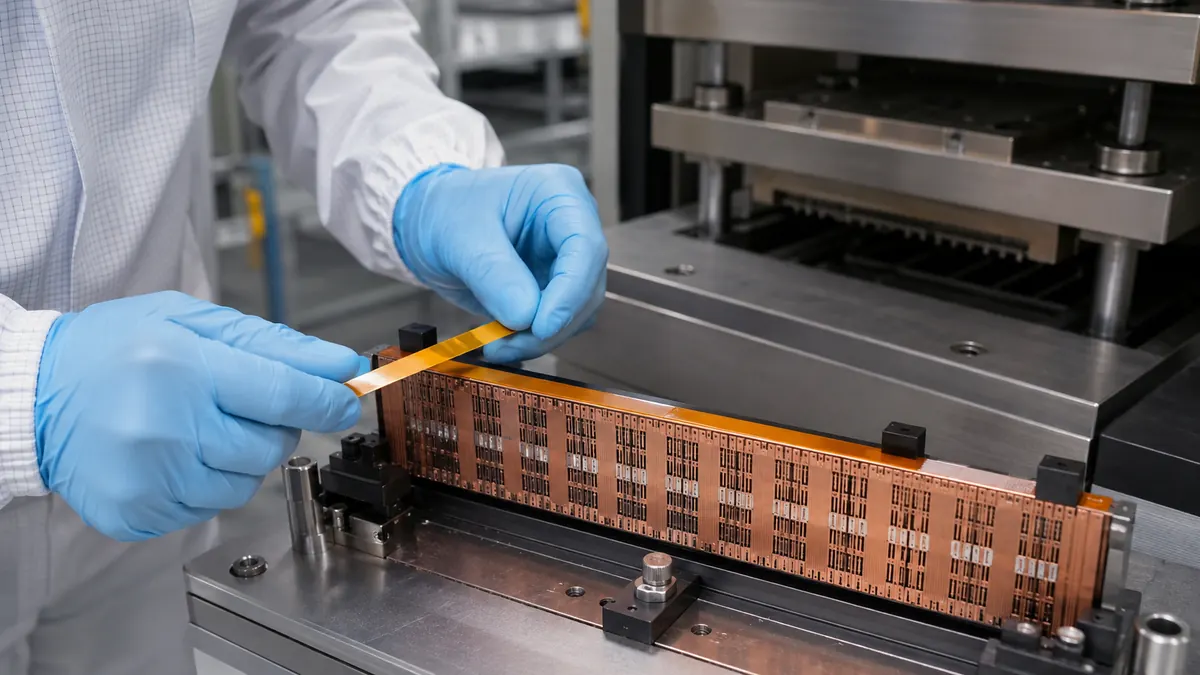
Polyimide tape for semiconductor leadframe molding protection can temporarily shield an approved leadframe surface, control selected resin-flash paths, or protect a defined handling area before transfer molding. The mask must be designed around the actual strip, die, mold chase, compound, temperature cycle, adhesion window, and downstream removal process.
Quick Answer
Use polyimide tape only when the package or process owner has identified a specific temporary masking function on the leadframe strip, carrier, or approved tooling interface. The film can provide a thin, heat-resistant backing, while the adhesive holds the mask during loading and thermal exposure. It cannot correct a damaged strip, worn mold, incorrect clamp condition, poor compound control, or an undefined flash problem.
Define the Leadframe Masking Role
A leadframe may pass through plating, die attach, wire bonding, transfer molding, deflashing, trim and form, marking, and inspection. A temporary tape mask must fit into that released sequence without contaminating bondable, solderable, plated, optical, or sealing surfaces. Possible functions include covering a defined back-side strip area, reducing compound contact on a nonfunctional carrier region, or protecting an approved handling surface.
The mask should never bridge a feature that controls mold closure or package thickness. It must also stay clear of wire-bond regions, die-pad interfaces, indexing holes, strip transport rails, tie bars, critical lead roots, and any surface that later requires plating, solderability, or electrical contact.
| Location | Possible controlled function | Boundary to protect |
|---|---|---|
| Back-side carrier zone | Temporary surface protection during a qualified mold cycle | Keep away from package seating and clamp lands |
| Strip edge | Define an approved resin or handling boundary | Do not cover transport, indexing, or datum features |
| Tool-contact interface | Protect only where the process drawing permits tape | Do not change mold gap or pressure distribution |
| Post-mold removal tab | Create controlled peel access | Keep clear of leads and fragile molded edges |
Select the Polyimide Tape Construction
Evaluate backing and adhesive as one system
Polyimide film is valued for low thickness, dimensional stability, and resistance to selected process temperatures. Adhesive chemistry governs tack, flow, residue, peel force, and compatibility with copper alloys, plating, mold compounds, release agents, cleaners, and storage conditions. Approve the exact construction and lot-control method; amber color alone is not a specification.
Control total thickness and edge profile
A thicker tape may be easier to handle but can create an unacceptable step at a mold interface. A very thin tape may stretch, curl, or wrinkle during manual placement. Specify total thickness, width, edge quality, splice policy, roll winding, liner if used, and allowed edge lift together with the mask drawing.
Match adhesion to the removal window
The mask must remain seated through transport and the validated thermal cycle, then release without lifting plating, bending leads, leaving adhesive, or scattering fragments. Test removal at the actual strip temperature and dwell time rather than relying on a room-temperature peel check.
| Selection input | Information to record | Why it matters |
|---|---|---|
| Leadframe | Alloy, plating, surface condition, thickness, strip flatness | Controls adhesion, contact, and peel sensitivity |
| Molding process | Compound, chase, temperature, pressure, time, release chemistry | Defines thermal and chemical exposure |
| Mask format | Roll, pre-cut strip, die-cut shape, liner, tab, packaging | Affects placement repeatability and contamination control |
| Geometry | Datum, width, overlap, edge setback, tolerance, thickness | Determines whether the mask enters a critical interface |
| Removal | Temperature, peel angle, support, rate, disposal, inspection | Controls lead load and residue risk |
Design a Repeatable Mask Geometry
Create a dimensioned mask drawing tied to stable leadframe or carrier datums. Define the start edge, side-to-side position, maximum overlap, edge setback, non-adhesive pull tab, and all keep-outs. Rounded die-cut corners can reduce local lifting, while a split liner may allow the operator or placement system to expose only the portion needed for initial registration.
Where a continuous strip is used, define allowable web tension, strip flatness, and cut location. Where individual pieces are used, control orientation and packaging so adhesive faces do not collect particles. Vision or mechanical poka-yoke may help, but the inspection method must detect both missing and misaligned masks.
Recommended Process Workflow
- Verify revisions. Match leadframe, package, mold tool, compound, tape, and work instruction.
- Inspect the strip. Check flatness, burrs, plating, contamination, and transport damage before masking.
- Prepare controlled masks. Use approved roll or die-cut packaging in the defined clean area.
- Locate the datum. Align without covering indexing holes, clamp lands, lead roots, or bondable surfaces.
- Apply uniform pressure. Seat the tape without stretching the strip or creating trapped air.
- Confirm position. Inspect edge setback, wrinkles, overlaps, tabs, and part count before molding.
- Run the released cycle. Do not compensate for a poor mask by changing mold parameters informally.
- Remove and inspect. Support the strip, peel as defined, count masks, and examine protected surfaces.
Validate the Complete Packaging Sequence
Qualification should use representative leadframe lots, plating conditions, strip positions, mold cavities, compound batches, temperature histories, mask tolerances, and removal conditions. Inspect both the intended protected area and neighboring functional surfaces. Final acceptance belongs to the package owner and should follow the applicable drawing, process controls, and reliability plan.
- Measure placement capability against the defined mask datum and keep-outs.
- Inspect mold fill, voids, short shots, flash, bleed paths, package dimensions, and edge condition.
- Check tape residue, discoloration, fragments, plating disturbance, bent leads, and strip flatness.
- Verify downstream trim, form, cleaning, marking, solderability, electrical test, and visual inspection as applicable.
- Requalify changes to tape, liner, width, die-cut tooling, leadframe finish, compound, mold, or removal method.
Troubleshooting Common Masking Defects
| Observed issue | Check first | Corrective direction |
|---|---|---|
| Tape shifts before molding | Tack, surface, web tension, placement pressure, handling | Restore the qualified preparation and locating method |
| Compound crosses the mask edge | Edge contact, wrinkle, geometry, clamp condition, mold wear | Separate tape-placement defects from tooling or process causes |
| Residue remains after peel | Adhesive, dwell, compound chemistry, temperature, peel rate | Screen the exact construction and removal window |
| Leadframe bends on removal | Peel angle, tab position, support, adhesion, strip thickness | Lower removal load and support the strip under approval |
| Mask creates dimensional interference | Total thickness, overlap, edge step, mold contact zone | Redesign the controlled boundary before further trials |
Related Products and Articles
Frequently Asked Questions
Can polyimide tape eliminate mold flash by itself?
No. Flash can involve mold condition, clamping, compound flow, strip flatness, and process settings. Tape is only a qualified local mask where the package design permits it.
Can the tape touch plated leads?
Only where the released drawing and qualification allow contact. Bondability, solderability, electrical contact, appearance, and residue requirements must remain protected.
Should the mask be a roll-fed strip or a die-cut part?
Choose from geometry, tolerance, contamination control, automation, liner handling, placement capability, and cost. Test the actual format, not only the base tape.
When should the tape be removed?
The package owner should define removal relative to cooling, deflashing, cleaning, trim and form, and inspection. Temperature and dwell can change peel behavior.
What belongs in a leadframe masking RFQ?
Provide strip and package drawings, alloy and finish, mask function, mold process, compound, temperature cycle, clean-area needs, geometry, volume, and validation criteria.
Build a Controlled Leadframe Masking Trial
Share the leadframe strip and package geometry, plating, mask boundary, mold interface, compound and cycle, removal sequence, cleanliness controls, annual volume, and acceptance plan. JIAO TAO TAO can help shortlist polyimide tape and converted-part formats for engineering evaluation.
Discuss leadframe maskingPTFE Tape for Side-Seal Bag-Making Machine Heater Bars
PTFE Tape for Thermoforming Heater Plate Release Surfaces
Related Article
Need help choosing the right industrial tape?
Send us your application details, including temperature, surface material, size, quantity and current problem. Our team will help recommend a suitable tape material or custom die-cut solution.

simon@jiaotaotao.com


+86-136 1277 5969


+86-136 1277 5969
