
PTFE Tape for Shrink-Wrap L-Sealer Release Surfaces
Technical Insights · Shrink Packaging Equipment
PTFE Tape for Shrink-Wrap L-Sealer Release Surfaces
PTFE tape for shrink-wrap L-sealers can provide a replaceable low-stick cover on an equipment surface that the machine manufacturer permits. Reliable maintenance depends on the exact sealing-bar arrangement, tape construction, strip width, joint position, heat history, film path, and replacement method—not on fitting brown tape to every hot part.
Replaceable release face on an approved stationary rail
Wrinkles, exposed adhesive, seam marks, or changed seal geometry
Machine location, PTFE construction, width, thickness, and joint
Film release, seal quality, cutting, temperature, and wear
Quick Answer
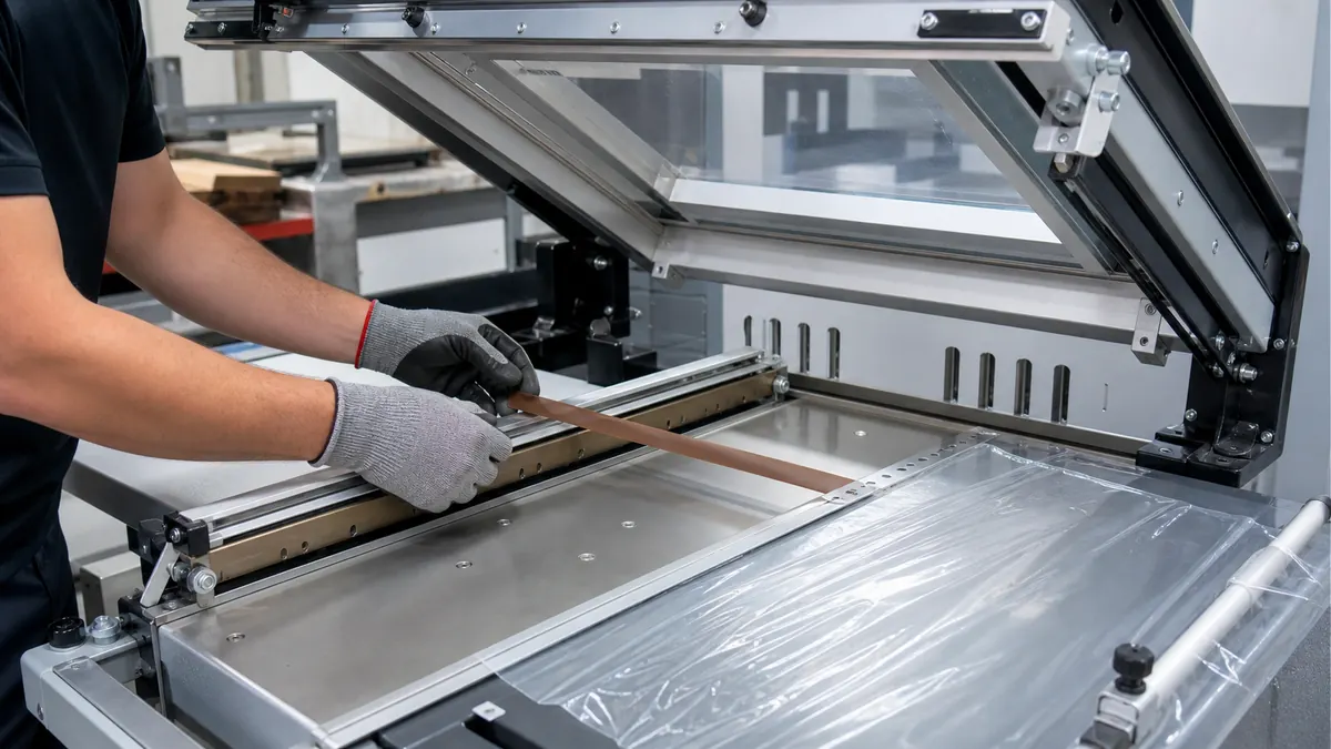
An adhesive-backed PTFE film or PTFE-coated fiberglass tape may be used on a stationary sealing support, pressure pad cover, guide, or other released contact area of a shrink-wrap L-sealer. It must not be assumed to repair a damaged heater, cutting wire, blade, pressure pad, sensor, guard, or electrical insulation. Begin with the machine manual and original assembly, identify the permitted tape location, then qualify the new strip with the production film, pack, temperature, dwell, pressure, and cooling sequence.
Map the L-Sealer Before Selecting PTFE Tape
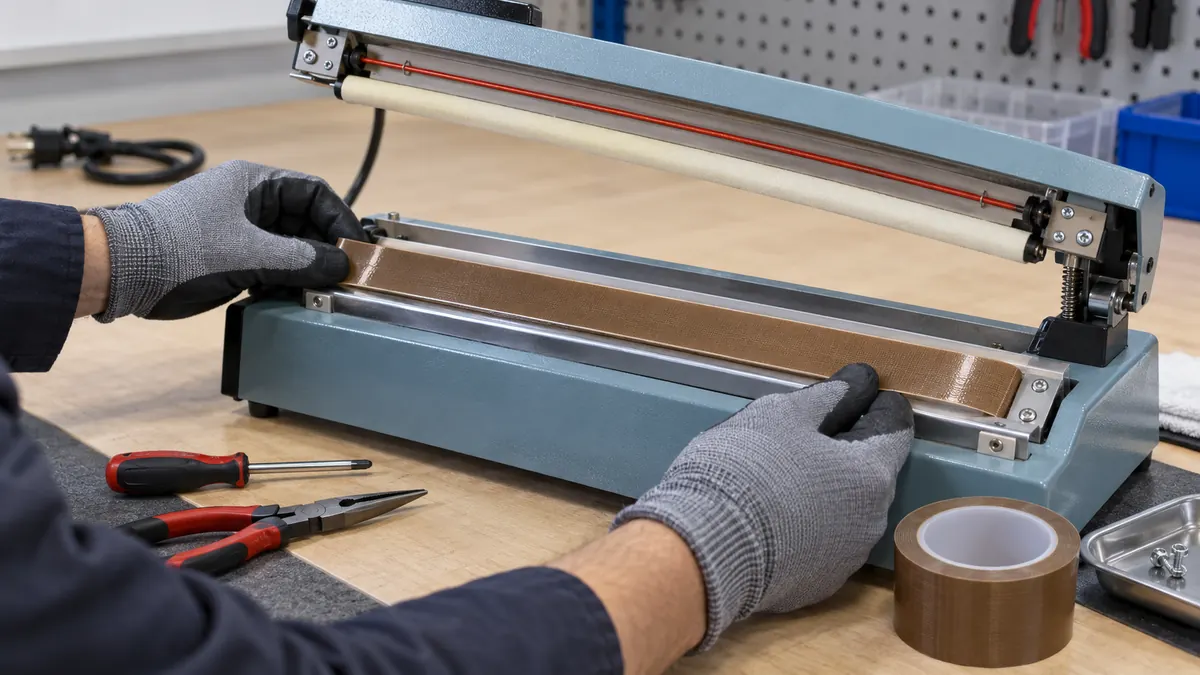
An L-sealer makes two perpendicular seals around a product wrapped in shrink film. Depending on the design, a heated wire, hot knife, impulse element, or constant-temperature system closes against a pressure surface. PTFE material may be adhesive-backed, mechanically retained, integrated into a pad, or supplied as a machine-specific replacement. These formats are not automatically interchangeable.
Trace the film path and identify the exact part that receives the strip. Record where the film touches, where the seal forms, which edge cuts, how the arm closes, and what clearance is available. Extra thickness or a raised overlap can change contact pressure, cut timing, seal width, and film release.
| Machine location | Possible PTFE role | Primary check |
|---|---|---|
| Stationary seal rail | Low-stick cover beneath an approved sealing element | Width, flatness, support, and element arrangement |
| Pressure pad cover | Protect a resilient pad from hot film transfer | Compression, retention method, and pad condition |
| Film guide or table edge | Reduce drag at a released contact point | Travel direction, wear, and exposed adhesive |
| Moving arm component | Only a machine-approved replacement format | Mass, clearance, retention, wiring, and guarding |
| Cutting or heating element | Not a repair surface | Use the specified element and insulation assembly |
Compare PTFE Tape Constructions
PTFE film tape
Skived PTFE film can provide a smooth, thin release surface on a supported stationary location. Screen puncture resistance, edge curling, adhesive support, and removal from the exact rail finish. A thin face may preserve geometry, but it can be less tolerant of burrs or damaged hardware.
PTFE-coated fiberglass tape
Reinforced fabric constructions add dimensional stability and handling strength. Their woven texture and total thickness can influence seal appearance or pressure distribution, especially where the covered surface sits directly beneath the film. Inspect both the sealed package and the tape after the trial.
Machine-specific covers
Some L-sealers use a mechanically retained PTFE cloth, sleeve, pad assembly, or preformed replacement strip. If the original design is not adhesive-backed tape, substituting a generic roll can change retention and safety. Use the approved replacement route unless the equipment owner releases an alternative.
| Specification input | What to record | Why it matters |
|---|---|---|
| Machine and location | Model, rail drawing, original parts, and approved tape position | Defines whether adhesive tape is the correct format |
| Operating cycle | Measured surface temperature, dwell, pressure, and starts/stops | Controls thermal and mechanical exposure |
| Shrink film | Polymer, thickness, printed area, folds, and contamination | Affects sticking, seal, cutting, and marks |
| Geometry | Rail widths, L-corner, holes, element path, and thickness limit | Prevents interference with the sealing stack |
| Maintenance | Cleaner, removal tools, inspection interval, and acceptance | Controls wear and safe replacement |
Design the L-Corner and Tape Joints
The inside corner is a critical transition. Folding one strip can create wrinkles or stretched edges, while two strips can leave a gap or overlap step. Choose a machine-approved joint that remains flat and keeps adhesive away from the film path. If two strips meet, document which strip terminates first, whether the joint is butted or overlapped, and where any step sits relative to the seal.
Do not stretch the backing to force it around the corner. Stored tension can lift an edge after heat-up. Rounded corners or converted shapes may improve repeatability when the rail geometry allows them. Keep cut edges clean and fully supported; adhesive exposed beside the release face can collect film fragments and dust.
Recommended Replacement Workflow
- Confirm the maintenance authority. Review the manual, released work instruction, and correct replacement construction.
- Isolate and cool the machine. Secure the arm and verify the safe state.
- Inspect before removal. Record wear, edge lift, contamination, joint position, and seal defects.
- Remove the old cover carefully. Protect the heater, wire, blade, pad, sensor, and rail finish.
- Clean by the approved method. Do not use a metal scraper or solvent that can damage the assembly.
- Inspect the underlying parts. Replace damaged elements, insulation, pads, or hardware separately.
- Measure and cut the strip. Use the released width and joint layout; keep edges square and supported.
- Apply without stretching. Align from a fixed datum and press progressively to avoid trapped air.
- Inspect the complete L path. Check wrinkles, exposed adhesive, joint height, clearances, and guarding.
- Run the approved verification. Start at the released setup and confirm seal, cut, release, and package appearance.
Validate the Tape with the Packaging Process
Use representative empty and filled packs, the thinnest and thickest approved film, difficult product profiles, planned line speeds, warm-up, steady running, restarts, and the expected maintenance interval. Include the L-corner because it can fail differently from straight rails. Record actual machine settings and observed surface condition rather than relying on a tape catalog limit alone.
- Inspect seal continuity, width, strength, cut separation, wrinkles, and burn-through using the package owner's methods.
- Check whether film catches on a leading edge or transfers residue to the release surface.
- Observe pressure and closure without defeating guards or bypassing interlocks.
- Inspect tape after hot and cold cycles for lift, shrinkage, abrasion, bubbles, and adhesive exposure.
- Requalify changes to tape, film, rail, heater, pad, cleaner, settings, joint design, or maintenance interval.
Troubleshooting L-Sealer Release-Surface Problems
| Observed problem | Check first | Corrective direction |
|---|---|---|
| Film sticks to the rail | PTFE wear, contamination, settings, film, pressure, and cooling | Correct the process cause and replace the cover if worn |
| Seal is weak or incomplete | Element, temperature, dwell, pressure, pad, and added thickness | Restore the machine stack and validate the setup |
| Corner seal is marked | Joint step, wrinkles, gap, alignment, and corner geometry | Revise the released corner detail |
| Tape edge lifts | Stretch, surface preparation, heat, contamination, and edge support | Remove stored tension and requalify the strip |
| Adhesive collects debris | Strip width, cut edge, rail coverage, and squeeze-out | Fully support adhesive and keep it outside the film path |
Frequently Asked Questions
Can PTFE tape be used on every shrink-wrap L-sealer?
No. Use it only in a location and format permitted by the machine manufacturer or released by the equipment owner. Some machines require a mechanically retained cover or machine-specific assembly.
Is PTFE film tape better than PTFE-coated fiberglass tape?
Neither is universally better. Film tape can be smoother and thinner; coated fiberglass adds reinforcement. Compare thickness, texture, puncture risk, joint behavior, and seal results on the actual machine.
Should the two strips overlap at the L-corner?
Only if the released joint design permits an overlap. An overlap adds a pressure step, while a butt joint may open. Validate the corner with production film and seal checks.
How often should the PTFE cover be replaced?
Use condition-based limits plus a planned inspection interval. Replace it before lift, wrinkles, cuts, deposits, exposed adhesive, or surface wear can affect safety or package quality.
What information belongs in an RFQ?
Provide the machine and approved location, rail dimensions, original cover arrangement, temperature and cycle, film types, joint design, cleaner, quantity, and validation plan.
Plan an L-Sealer Release-Surface Trial
Share the approved contact surface, machine arrangement, rail drawing, measured operating window, shrink-film structure, joint limits, cleaning method, and acceptance checks. JIAO TAO TAO can help shortlist a PTFE film or reinforced construction for controlled maintenance evaluation.
Polyimide Tape for Wave Solder Connector Shielding
Polyimide Tape for Motor Slot Wedge Retention Before VPI
Related Article
Need help choosing the right industrial tape?
Send us your application details, including temperature, surface material, size, quantity and current problem. Our team will help recommend a suitable tape material or custom die-cut solution.

simon@jiaotaotao.com


+86-136 1277 5969


+86-136 1277 5969
