
Polyimide Tape for Hairpin Motor Winding Joint Insulation
Polyimide Tape for Hairpin Motor Winding Joint Insulation
Polyimide tape for hairpin motor winding joints can provide a thin protective wrap around selected conductor transitions, welded ends, lead exits, or localized insulation interfaces. It is not a replacement for the motor's engineered insulation system. Film thickness, adhesive, edge coverage, overlap, application tension, varnish compatibility, and thermal processing must be evaluated on the actual stator and winding process.

Key Takeaways
- Define whether the tape is for temporary holding, edge protection, spacing, or part of a qualified insulation build.
- Round, shield, or otherwise control sharp conductor and weld features before relying on a thin film wrap.
- Use an overlap and application method that can be repeated without wrinkles, trapped air, or excessive tension.
- Validate the completed stator through the motor manufacturer's electrical, thermal, chemical, vibration, and manufacturing tests.
Where Polyimide Tape May Fit in a Hairpin Motor Stator
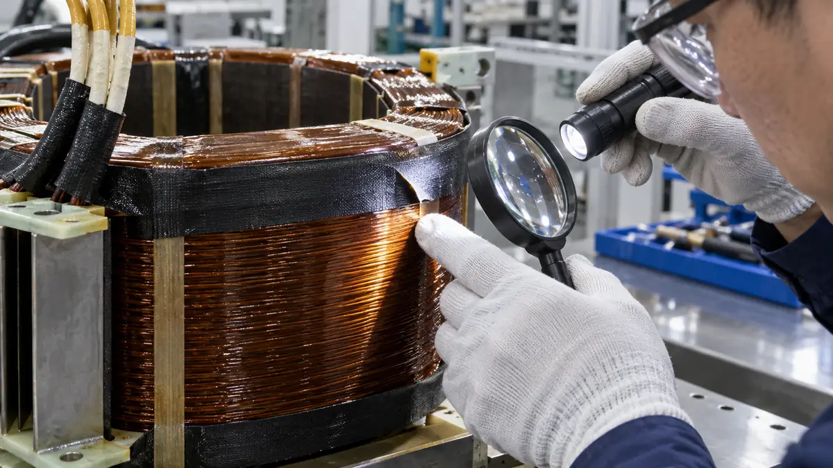
Hairpin windings use formed conductors inserted into stator slots and joined at the end winding. The resulting assembly can include conductor bends, welded or brazed joints, phase connections, bus connections, lead exits, and tightly spaced areas near steel or adjacent conductors. Polyimide film tape is considered where a thin, heat-resistant and electrically insulating wrap is useful around a localized feature.
The tape's exact role must be documented. It may hold another insulation component during assembly, provide a controlled film barrier around a smooth joint, protect an edge during subsequent handling, or support spacing at a lead transition. The motor's insulation coordination, creepage and clearance, partial-discharge behavior, thermal class, impregnation process, and service environment remain system-level design decisions.
Single-Layer, Overlap, and Shaped Parts Compared
| Format | Potential use | What to control |
|---|---|---|
| Single localized wrap | Temporary holding or a defined film barrier on a smooth feature | Start and finish position, edge coverage, adhesion, and lift |
| Spiral or overlapping wrap | Longer conductor transition where continuous coverage is needed | Overlap percentage, tension, build variation, wrinkles, and termination |
| Flag or tab wrap | Localized identification, holding, or protection near a lead exit | Flag length, flutter, clearance, adhesive exposure, and handling |
| Die-cut polyimide piece | Repeatable coverage around a specific joint or terminal geometry | Drawing tolerance, liner, orientation, fold line, and placement fixture |
| Double-sided polyimide construction | Bonding a separate insulation part where heat resistance is required | Total thickness, both substrates, adhesive flow, and permanent stress |
Specification Inputs for Hairpin Joint Tape
| Input | Details to record | Selection impact |
|---|---|---|
| Joint geometry | Conductor dimensions, bend radius, weld profile, corner condition, adjacent parts, and available access | Defines width, conformability, and wrap method |
| Electrical role | Potential difference, insulation coordination, spacing, test voltage, and system acceptance criteria | Determines whether tape is supplemental or part of an approved system |
| Thermal profile | Assembly heating, impregnation cure, operating cycles, hot spots, and exposure duration | Guides film, adhesive, and process screening |
| Chemical exposure | Cleaning agents, flux or welding residue, varnish or resin, oils, coolants, and humidity | May affect adhesion, swelling, residue, and long-term integrity |
| Mechanical load | Winding movement, vibration, insertion contact, fixture pressure, and downstream handling | Defines edge protection and abrasion requirements |
| Application process | Manual, semi-automatic, or automated; tape width; tension; turns; overlap; and termination | Controls repeatability and cycle time |
| Inspection | Coverage, wrinkles, bubbles, lifted edges, exposed conductor, spacing, and electrical tests | Creates measurable line acceptance criteria |
How to Select the Tape Construction
Match the adhesive to the real thermal and chemical sequence
Polyimide film is selected for demanding temperature environments, but the complete tape includes an adhesive whose behavior must be evaluated separately. Review the assembly heating cycle, varnish or resin contact, cleaning process, dwell time, storage, and service exposure. Request the exact product data and test samples through the production sequence.
Choose width from coverage and access
A wider tape can reduce the number of turns but may bridge a radius or wrinkle around a compact joint. A narrow slit roll may conform more easily yet require tighter overlap control. Select width using the actual conductor geometry, neighboring joints, tooling clearance, and operator or applicator access.
Control edges before applying a thin film
Thin tape cannot safely neutralize a sharp weld projection or burr by itself. Inspect and control the joint profile using the motor manufacturer's process. Where additional mechanical protection or spacing is required, a formed insulation component, sleeve, coating, or other approved construction may be needed.
Consider die-cut parts for repeatable localization
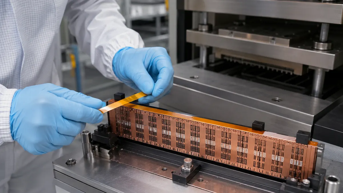
When the same compact joint needs a defined patch or fold, a liner-supported die-cut part can reduce operator variation. The drawing should define adhesive and non-adhesive zones, fold direction, datum, liner tab, orientation, and packaging. It still needs qualification as part of the complete insulation system.
Recommended Application and Validation Workflow
- Define the tape function. State whether it provides holding, abrasion protection, a localized film barrier, spacing support, or another controlled role.
- Inspect the conductor joint. Confirm weld profile, burr control, cleanliness, oxidation, and the approved surface-preparation method.
- Select trial formats. Compare film thickness, adhesive type, tape width, liner, and die-cut geometry without changing several variables at once.
- Document the wrap method. Set the start point, direction, tension, overlap, number of turns, edge coverage, and termination.
- Use production-representative access. Apply samples on an actual stator or fixture so neighboring joints and tooling constraints are included.
- Inspect immediately. Check wrinkles, bubbles, bridging, exposed conductor, lifted edges, and spacing to adjacent features.
- Run downstream processing. Include impregnation, cure, thermal cycles, mechanical handling, and all required cleaning or fluid exposures.
- Complete system tests. Use the motor owner's electrical, thermal, vibration, aging, and destructive-analysis plan before release.
Troubleshooting Table
| Issue | Tape checks | Process checks |
|---|---|---|
| Edge lift after cure | Adhesive compatibility, overlap, termination, width, and thermal exposure | Surface residue, application pressure, cure fixture, and conductor stress |
| Wrinkles at the joint | Film thickness, width, conformability, and liner handling | Wrap angle, tension, joint radius, access, and applicator path |
| Film damage over a weld | Layer count, backing thickness, abrasion resistance, and edge coverage | Weld projection, burr control, handling contact, and fixture interference |
| Variable insulation build | Tape caliper, overlap tolerance, slit width, and adhesive flow | Turns, tension, operator method, and termination location |
| Contamination under the wrap | Roll cleanliness, packaging, and exposed adhesive handling | Joint cleaning, gloves, workstation control, and storage time |
Do not publish or use generic dielectric, temperature, or lifetime values as if they approve the final motor. Obtain data for the exact tape construction and test the released winding assembly under its defined electrical and environmental conditions.
Related Products and Articles
- Review the polyimide tape product family and available formats.
- Compare material structures in the polyimide tape properties and selection guide.
- Explore die-cut polyimide parts for repeatable localized insulation.
- Send the joint drawing and process sequence for a tape-format review.
Frequently Asked Questions
Can polyimide tape insulate a hairpin motor winding joint?
It may serve as a localized film wrap or supplemental insulation when the motor design specifies it. The complete winding insulation system, joint profile, spacing, impregnation, and electrical tests determine suitability.
Should polyimide tape be applied before or after varnish impregnation?
The sequence depends on the approved motor process and tape compatibility. Test adhesion, wetting, cure exposure, edge lift, and electrical performance through the exact impregnation sequence.
How much overlap should be used?
There is no universal overlap. Define it from the required coverage, joint geometry, insulation build, tape width, tension, and validated application method, then control it in the work instruction.
Can a die-cut polyimide patch replace a spiral wrap?
A shaped patch may improve repeatability on a compact joint, but coverage, folding, edges, liner removal, and downstream processing must be validated. It is an alternative format, not an automatic substitute.
What information should a motor manufacturer provide to a tape supplier?
Provide the joint drawing, conductor and coating details, tape function, temperature and cure profile, chemicals, available space, wrap method, required format, quantities, and system-level qualification requirements.
Plan a Hairpin Joint Insulation Trial
Share the conductor and joint geometry, insulation role, thermal sequence, impregnation chemistry, tape width limits, application method, quantity, and acceptance tests. JIAO TAO TAO can help prepare candidate polyimide tape or die-cut formats for your own motor qualification.
Contact the technical team about hairpin winding joint insulation.
PTFE Tape for Continuous Band Sealer Heating Blocks
PTFE Tape for Rubber Vulcanizing Press Platen Release
Related Article

Need help choosing the right industrial tape?
Send us your application details, including temperature, surface material, size, quantity and current problem. Our team will help recommend a suitable tape material or custom die-cut solution.

simon@jiaotaotao.com


+86-136 1277 5969


+86-136 1277 5969
