
Polyimide Tape for Conformal Coating Connector Masking
Polyimide Tape for Conformal Coating Connector Masking
Polyimide tape for conformal coating masking protects connector mating faces, test points, switches, grounding pads, and other keep-out areas on a printed circuit board. Reliable masking depends on the complete coating and cure process: tape thickness, adhesive chemistry, edge sealing, removal timing, ESD controls, and the geometry of every protected feature must be validated together.
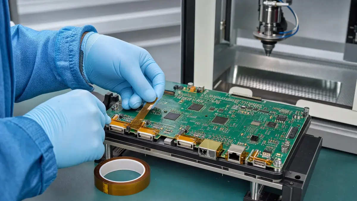
Why Connectors and Keep-Out Areas Must Be Masked
Conformal coating is intended to cover selected circuit-board surfaces, but it can interfere with parts that need electrical contact, movement, adjustment, or future connection. Connector contacts and mating surfaces must remain usable. Test pads may need probe access. Switches, sockets, grounding areas, and selected thermal interfaces may also have coating restrictions defined by the assembly drawing.
A mask establishes that boundary during spray, dip, brush, or selective-coating processes. The tape must stay sealed while coating is applied and cured, then remove without pulling components, tearing into fragments, leaving unacceptable residue, or damaging the coating edge.
Map the Keep-Out Zone Before Choosing Tape Width
Do not mask from visual judgment alone. Use the approved PCB drawing, coating specification, or manufacturing work instruction to define the protected area. Distinguish between the connector body, the actual mating face, solder joints that may need coating, nearby test points, and any capillary path where liquid can migrate under or around the mask.
Board-edge connectors
For rectangular connector shells or contact openings, tape can be slit to width or converted into a shape that covers the mating face while leaving required solder fillets exposed. The tape edge should not rest on fragile components or bridge across a gap that cannot be pressed down.
Test points and small pads
Die-cut dots or tabs can improve repeatability where many small circular or rectangular areas must remain accessible. A common carrier can present multiple masks in the correct sequence and reduce loose-part handling.
Polyimide Tape Selection Checklist
| Selection item | Process concern | Validation question |
|---|---|---|
| Film and total thickness | Affects conformity, edge definition, and clearance around components | Can the tape seal the feature without bridging or loading nearby parts? |
| Adhesive system | Determines adhesion, chemical compatibility, and removal behavior | Does it remain stable through coating exposure and the complete cure profile? |
| Surface cleanliness | Flux residue, dust, oil, or moisture can create edge lift | Is the board in the approved pre-coating condition when tape is applied? |
| ESD requirement | Standard tape should not be assumed to provide controlled static behavior | Does the work instruction require a documented antistatic grade and handling method? |
| Die-cut quality | Small particles or adhesive strings can contaminate an electronics process | Are edges clean and are masks presented in a controlled liner format? |
| Removal timing | Coating condition affects edge tearing and cleanup | At which verified stage does the mask release cleanly without damaging the coating boundary? |
Polyimide Tape Compared with Other Masking Methods
| Masking method | Useful characteristics | Points to verify |
|---|---|---|
| Polyimide film tape | Thin, dimensionally stable, visible, and available in narrow or die-cut formats | Coating compatibility, cure profile, edge seal, residue, and ESD requirement |
| Custom die-cut polyimide mask | Repeatable geometry for connectors, pads, and multiple keep-out areas | Tolerance, liner release, registration, and waste removal |
| Reusable cap or plug | Useful for three-dimensional ports or repeated production | Fit, cleaning, handling, storage, and coating entry paths |
| Peelable masking material | Can cover irregular geometry without tape joints | Cure, complete removal, compatibility, application control, and contamination risk |
| Selective coating fixture | Can reduce manual masking in stable high-volume processes | Capital cost, board variation, maintenance, and fixture shadowing |
Application Procedure for Connector Masking
- Confirm the coating keep-out drawing. Identify the mating surface, test areas, switches, sockets, and other protected features.
- Verify board readiness. Follow the approved cleaning, drying, and handling process before masking.
- Select the correct mask format. Use a slit width, folded tab, plug, or die-cut piece that covers the functional area without unnecessary overlap.
- Apply without tension. Place the film onto the feature rather than stretching it across the connector.
- Seal the perimeter. Press accessible edges using a controlled tool that will not damage components or solder joints.
- Inspect before coating. Check for gaps, wrinkles, lifted corners, misplaced masks, missing pads, and tape touching moving parts.
- Remove at the approved point. Pull at a controlled angle and support the connector or board where needed.
- Inspect the boundary. Confirm the mating face is clear and the adjacent coating is continuous to the specified line.
Common Defects and Corrective Checks
| Observed defect | Possible contributors | First checks |
|---|---|---|
| Coating beneath the tape edge | Contamination, bridging, poor edge pressure, or coating flow path | Review surface condition, geometry, press-down access, and application tension |
| Mask lifts during cure | Unsuitable adhesive, trapped stress, heat exposure, or low-contact area | Compare the full cure profile and tape construction on representative boards |
| Coating edge tears on removal | Removal timing, excessive film thickness, or uncontrolled pull direction | Establish a verified removal window and peel method |
| Adhesive residue | Surface interaction, cure conditions, dwell time, or wrong tape grade | Review supplier data and repeat the complete process trial |
| Connector body is damaged | Excessive tape force, poor access, or removal load | Use a pull tab, smaller mask, support fixture, or alternative cap design |
Approval Testing and Change Control
A production trial should include the actual board finish, connector materials, cleaning process, coating chemistry, application method, coating thickness target, flash-off, cure schedule, and removal stage. Inspect coating intrusion, mask movement, residue, coating-edge quality, connector function, test-point accessibility, and any particle or ESD concerns. Record the approved tape construction and process window; amber color or the word “polyimide” is not a substitute for a controlled specification.
Related Tape Resources
- Compare polyimide tape constructions for electronics masking and insulation.
- Review polyimide tape properties, uses, and selection factors.
- Send your PCB keep-out drawing and coating process for tape-format review.
Frequently Asked Questions
Can ordinary polyimide tape mask every conformal coating?
No. Coating chemistries, solvents, application methods, cure profiles, substrates, and removal stages vary. Validate the exact tape and process combination.
Should connector solder joints also be masked?
Only if the approved coating drawing requires it. The mating face may need protection while selected solder joints still require coating coverage, so the mask boundary must follow the functional specification.
Is all amber polyimide tape ESD safe?
No. Color does not establish static-control performance. If the process requires an antistatic grade, obtain the relevant supplier data and use the approved ESD handling method.
When should conformal-coating masks be removed?
The best point depends on the coating and cure process. Establish a removal window during trials that preserves the coating edge and allows clean mask release.
Are die-cut masks better than narrow roll tape?
They can improve repeatability and speed when the same connectors or pads are masked on every board. Roll tape remains useful for prototypes, repairs, and frequently changing geometries.
Specify a PCB Masking Format for Your Coating Line
Share the keep-out drawing, board and connector materials, coating chemistry, application method, cure profile, ESD requirement, removal stage, and preferred roll or die-cut presentation. The JIAO TAO TAO team can help prepare candidate polyimide tape formats for your own process validation.
PET Silicone Tape for High-Temperature Release Liner Splicing
PET Silicone Tape for E-Coat Masking
Related Article
Need help choosing the right industrial tape?
Send us your application details, including temperature, surface material, size, quantity and current problem. Our team will help recommend a suitable tape material or custom die-cut solution.

simon@jiaotaotao.com


+86-136 1277 5969


+86-136 1277 5969
