
Industrial Double-Sided Tape for Membrane Switch Assembly
Industrial Double-Sided Tape for Membrane Switch Assembly
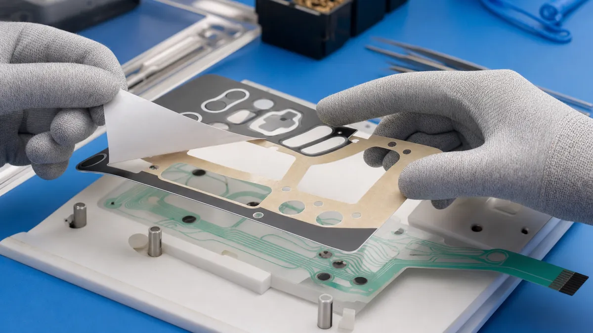
Industrial double-sided tape for membrane switch assembly bonds the graphic overlay, spacer, dome-retainer, circuit, and rear adhesive layers while maintaining defined openings for keys, LEDs, windows, vents, and tails. Material selection must balance adhesion, thickness control, die-cut accuracy, liner handling, environmental exposure, and the assembly sequence.
Where Double-Sided Adhesive Fits in a Membrane Switch
A membrane switch is a laminated structure. The exact stack varies, but it can include a printed graphic overlay, overlay adhesive, dome or spacer layer, printed circuit, tail exit, and a rear mounting adhesive. Each adhesive layer has a different job. One may create the key cavity and control spacing, while another bonds the finished switch to an enclosure.
Using one tape specification for every layer can create avoidable problems. A thin spacer may not provide the required cavity, a soft adhesive can flow into openings, and a liner that is difficult to remove can slow assembly or damage narrow die-cut features. Define each layer by function before selecting a construction.
Key Selection Parameters
| Parameter | Effect on assembly | Validation question |
|---|---|---|
| Carrier type | Influences dimensional stability and die-cut handling | Does the layer hold its geometry during liner removal and placement? |
| Total thickness | Affects key travel, cavity height, stack-up, and enclosure fit | Does the complete laminated stack meet the drawing? |
| Adhesion to each substrate | Controls edge sealing and long-term bond | Has it been tested on the actual ink, film, circuit, and enclosure surface? |
| Shear and creep behavior | Influences alignment under load and temperature | Do apertures and edges remain stable after conditioning? |
| Die-cut tolerance | Controls key openings, windows, tail clearance, and registration | Can the converter hold the critical dimensions and burr requirements? |
| Liner and release level | Affects pick-up, placement, and automation | Can operators expose one side without distorting the part? |
| Environmental compatibility | Influences bond performance in the end-use environment | Has the finished stack been tested for the specified heat, humidity, chemicals, and cleaning? |
Comparing Common Double-Sided Tape Constructions
| Construction | Useful characteristics | Typical design questions |
|---|---|---|
| Double-sided PET carrier tape | Thin, dimensionally stable, and suitable for precision converting | Is the carrier thickness compatible with switch travel and openings? |
| Unsupported transfer adhesive | Very thin bond line and good conformity on flat surfaces | Can the adhesive be handled and die-cut without stretching or edge flow? |
| Tissue carrier tape | Conformable and economical for less dimension-critical lamination | Does it provide enough stability and environmental resistance? |
| Thin foam tape | Can fill small gaps and provide cushioning | Will compression change key feel, sealing, or overall thickness? |
Designing the Die-Cut Adhesive Layer
Openings and webs
Key cavities, LED windows, display openings, vents, connector zones, and tail paths need clear adhesive boundaries. Narrow webs must be wide enough to convert, strip, transport, and place without breaking. Very sharp internal corners can concentrate stress and complicate waste removal, so the converter should review the drawing before tooling.
Registration features
Tooling holes, external datum edges, camera-readable features, and assembly fixtures can improve layer-to-layer accuracy. Registration should reference the functional switch geometry rather than an inconsistent sheet edge. For manual assembly, split liners or extended pull tabs can expose adhesive in a controlled sequence.
Liner strategy
The release liner is part of the process. It supports the die-cut part, protects the adhesive, and determines how easily a layer can be picked and positioned. Consider which side should be laminated first, whether the part is supplied individually or in sheets, and how operators or equipment will remove the final liner.
Membrane Switch Lamination Workflow
- Approve the layer drawing. Confirm openings, datums, stack thickness, tail exit, and critical tolerances.
- Condition and clean materials. Keep films flat and follow the approved cleaning method for printed and unprinted surfaces.
- Fixture the first layer. Use registration pins or another validated datum without stretching the film.
- Expose the adhesive progressively. Peel a split liner in stages so the die-cut frame stays supported.
- Align before full contact. Check tooling holes, key centers, windows, and circuit features.
- Laminate with controlled pressure. Use a roller, press, or fixture appropriate for the construction and avoid trapping air.
- Inspect the stack. Verify alignment, edge seal, bubbles, liner fragments, adhesive intrusion, and tail freedom.
- Test the finished switch. Functional and environmental approval belongs to the complete assembled design, not the tape alone.
Common Assembly Problems and Corrective Checks
| Problem | Possible contributors | First checks |
|---|---|---|
| Misaligned key openings | Film stretch, weak datum, liner release force, fixture variation | Registration method, material conditioning, and placement sequence |
| Bubbles or silvering | Dust, uneven pressure, trapped air, surface texture | Cleaning, lamination direction, roller pressure, and adhesive choice |
| Edge lifting | Low surface energy, ink compatibility, contamination, insufficient bond area | Actual substrate tests, edge geometry, dwell, and pressure |
| Adhesive in windows or key cavities | Die-cut variation, adhesive flow, handling distortion | Tool condition, material construction, storage, and critical dimensions |
| Difficult liner removal | Incorrect release level, small pull area, narrow webs | Liner specification, pull tab design, and peel direction |
Prototype and Production Approval
Build prototypes with production-intent films, inks, circuits, adhesive layers, tooling, and lamination methods. Test the complete switch for actuation, visual quality, edge sealing, dimensional stability, mounting behavior, and the end-use environment specified by the customer. Record the approved construction and control material substitutions; two tapes with similar thickness may behave differently during converting and lamination.
Related Tape Resources
- Explore industrial double-sided tape constructions for lamination and mounting.
- Read a related guide to double-sided tape for appliance control panel bonding.
- For precision kiss-cutting, liner design, or sample sheets, send your membrane switch drawing and stack requirements.
Frequently Asked Questions
What double-sided tape is best for a membrane switch?
There is no universal best tape. Selection depends on the layer function, substrates, total thickness, key geometry, environment, converting method, and assembly sequence. Test the complete stack.
Can the same adhesive be used for the spacer and rear mounting layer?
Sometimes, but the functions are different. The spacer controls internal geometry, while the rear layer bonds to the customer's enclosure. Evaluate them separately before standardizing one construction.
Why are split liners useful?
A split liner lets an operator expose a controlled section, register the part, and then remove the remaining liner. This can reduce handling distortion on large or narrow die-cut frames.
How should adhesive openings be dimensioned?
Dimension them from functional datums and include tolerances for the film, printing, circuit, die cut, and assembly process. The converter should review narrow webs and critical clearances.
Does tape certification prove the membrane switch will pass environmental testing?
No. Supplier data can support material screening, but the completed membrane switch must be validated in its actual construction and end-use conditions.
Develop a Die-Cut Adhesive Layer for Your Membrane Switch
Share the layer drawing, substrate and ink information, required thickness, liner preference, assembly method, sample quantity, and end-use conditions. The JIAO TAO TAO team can help compare double-sided tape constructions and custom-converting options for your validation.
Industrial Double-Sided Tape for EMI Gasket Lamination
Custom Die-Cut Tape for Busbar Phase Isolation
Related Article

Need help choosing the right industrial tape?
Send us your application details, including temperature, surface material, size, quantity and current problem. Our team will help recommend a suitable tape material or custom die-cut solution.

simon@jiaotaotao.com


+86-136 1277 5969


+86-136 1277 5969
