
Custom Die-Cut Tape for LiDAR Sensor Window Bonding
Buying Guides · Precision Sensor Assembly
Keep the optical aperture clear.
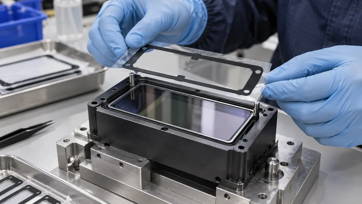
Custom die-cut tape for LiDAR sensor window bonding can position a thin optical cover, distribute assembly pressure, and simplify a repeatable perimeter bond. The adhesive frame must be designed around the real window material, housing finish, optical keep-out, environmental seal strategy, tolerance stack, cleaning method, and sensor validation—not selected from a generic “waterproof tape” claim.
Quick Answer
Specify the adhesive frame as one part of the complete optical-window joint. Begin with the aperture and keep-out, then define the bonded land, housing and window surfaces, required gap, compression path, environmental exposure, and assembly datum. A die cut can improve placement repeatability, but it cannot compensate for unstable molded geometry, contaminated optics, weak surface treatment, or an undefined seal path.
This guide is for LiDAR mechanical, optical, quality, and manufacturing engineers designing a perimeter joint outside the optical path. The calculation and trial record help translate an RFQ into measurable placement and qualification criteria; they do not prescribe a sensor's optical limits or claim an ingress-protection rating. Technical content reviewed: .
Define the Sensor-Window Joint Requirements
LiDAR assemblies can use glass, coated glass, polymer windows, optical filters, or multi-layer covers. Housings may be coated metal or engineering plastic. These surfaces differ in surface energy, thermal expansion, flatness, and sensitivity to cleaners. Record the actual supplier, coating, molding condition, texture, and allowable treatment rather than testing on an unrepresentative flat coupon.
| Design input | What to define | Why it matters |
|---|---|---|
| Optical aperture | Active field, border, keep-out, cleanliness, and allowable edge shadow | Sets the inner frame boundary |
| Bonded surfaces | Window material and coating; housing resin, coating, texture, and treatment | Controls adhesive screening and preparation |
| Joint geometry | Land width, gap, flatness, corner radius, step, and tolerance stack | Determines frame width and placement margin |
| Environment | Temperature, humidity, fluids, UV, vibration, shock, and pressure change | Defines aging and seal-system tests |
| Production | Cleanliness, throughput, fixture, press, liner removal, inspection, and rework | Controls format and handling features |
Choose the Adhesive Construction
Carrier and adhesive family
A film carrier can stabilize a thin frame and support clean die cutting. Foam can fill a larger gap and distribute pressure, but its compression set, thickness tolerance, edge visibility, and long-term behavior must fit the design. Transfer adhesive minimizes added carrier thickness but requires careful converting and handling.
Surface and optical compatibility
Screen the exact adhesive on production window and housing surfaces after the approved cleaning or treatment. Consider outgassing, fogging, migration, discoloration, and cleaner compatibility where the product owner requires them. Do not assume a clear adhesive is automatically optically clean or a black carrier is automatically light-tight.
Thickness and stress
Thickness affects gap filling, bond-line pressure, window position, housing closure, and stress during thermal expansion. Excessive stiffness or assembly pressure can distort a thin window or housing. Too little thickness can leave incomplete contact over texture or flatness variation.
Design the Die-Cut Frame and Liner
| Feature | Design question | Control |
|---|---|---|
| Inner aperture | What margin remains outside the optical keep-out at tolerance extremes? | Datum strategy, inner profile, and inspection gauge |
| Outer profile | Does the frame stay inside the housing land without an exposed edge? | Land tolerance, corner radius, and edge margin |
| Registration | How will the operator or robot locate the part? | Holes, notches, carrier, fixture pins, or vision features |
| Liner system | Which side applies first and how is each liner removed? | Split liner, extended tab, release balance, and static control |
| Piece handling | How are missing, doubled, stretched, or damaged frames detected? | Carrier pitch, count, orientation, and inspection plan |
Use stable product datums instead of decorative edges or a variable molded flash line. Rounded internal corners can reduce stress concentration and converting difficulty. Pull tabs should remain outside functional surfaces and must not create a path that compromises the seal design.
Calculate the Worst-Case Aperture and Outer-Edge Margin
In a local straight cross-section, let g be the nominal gap from the optical keep-out to the frame's inner edge and e the total inward error from the housing/optical datum, converted edge location, and placement. Minimum aperture margin is g − e. Evaluate the outer edge separately using its outward error. Add all relevant tolerances conservatively unless the product owner approves another statistical method; nominal CAD clearance alone does not show the worst case.
This two-dimensional example excludes corner rotation, window-to-housing offset not included in the datum term, frame stretching, thermal movement, adhesive flow, and local land variation. Add those effects where relevant and check the complete perimeter. If a margin fails, compare improved registration or revised land geometry before reducing the bond width; the latter changes the joint that must be mechanically and environmentally qualified.
| Trial field | What to enter | Evidence to request |
|---|---|---|
| Optical boundary | Window and housing revisions; optical keep-out; approved datums; minimum margin at each corner | Tolerance review plus inspection overlay or gauge |
| Material comparison | Candidate adhesive/carrier code; thickness and tolerance; exact coated window and housing surfaces | Current data sheet and results on production-representative substrates |
| Placement comparison | Fixture revision; liner sequence; tab direction; applied pressure method; dwell and conditioning | Position before and after liner removal, with stretched or doubled pieces identified |
| Functional gates | Specified optical test, mechanical retention, seal architecture, environmental sequence, and acceptance limits | Matched initial and post-exposure records for the same sample identity |
| Release decision | Required sample size; lots and geometry extremes; failed criterion; controlled next change | Signed qualification record rather than an unsupported “waterproof” statement |
The 3M VHB Tape Design Guide identifies substrate behavior, bond thickness, movement, and surface preparation as design inputs. Apply that joint-design reasoning to the actual candidate construction; the guide does not establish that a VHB grade or its published performance is suitable for this sensor.
Recommended Window-Bonding Workflow
- Confirm revision. Match window, housing, adhesive-frame drawing, surface treatment, and fixture.
- Control the environment. Use the released cleanliness, temperature, humidity, static, and handling conditions.
- Inspect both parts. Stop for particles, coating damage, distortion, oil, moisture, or molded defects.
- Prepare the surfaces. Apply only the approved cleaning and treatment method with verified dry time.
- Register the frame. Use pins, nest, vision, or another released datum without stretching the die cut.
- Apply controlled pressure. Wet out the complete land using the validated fixture and dwell.
- Remove the second liner. Pull in the approved direction while protecting the aperture and frame position.
- Place the window. Lower it squarely to avoid trapping particles or sweeping the adhesive inward.
- Inspect the joint. Check aperture clearance, bubbles, folds, exposed edges, position, and piece count.
- Condition and test. Observe the specified dwell before optical, leak, mechanical, or environmental evaluation.
Validate the Complete Sensor Assembly
Adhesion data alone cannot release the joint. Validate representative material lots, tolerance extremes, molded textures, coatings, operators, fixtures, pressure settings, dwell times, and aging exposures. Include the actual optical and sealing architecture, especially when another gasket, vent, coating, or mechanical clamp shares the environmental function.
| Validation group | Observe | Release evidence |
|---|---|---|
| Placement | Aperture margin, frame position, liner fragments, bubbles, and distortion | Vision limit, gauge, or approved image standard |
| Bond | Wet-out, peel or push resistance, creep, edge lift, and aging | Product-specific mechanical criteria |
| Optical | Transmission, reflection, contamination, calibration, and field performance | Sensor engineering test plan |
| Environment | Temperature cycling, humidity, fluids, UV, vibration, shock, and seal behavior | Released assembly qualification |
| Production | Cycle time, scrap, rework, traceability, fixture capability, and inspection | Production-equivalent pilot record |
Window-Joint Acceptance Record Template
Retain one traceable record per sample: sensor / window / housing revisions | coating and surface lots | adhesive code and lot | frame drawing and inspection report | fixture and liner sequence | measured inner and outer margins in mm | pressure method / conditioning | initial optical and seal results | exposure-plan revision | post-exposure optical / seal / retention results | specified limits | photos | decision / reviewer / date. Optical results should use the sensor owner's specified wavelengths, angles, and calibration method. Record a missing required test as “not tested” and keep the candidate on hold.
SCHOTT's sensing and vision guidance describes the role of glass transmission and surface/coating compatibility in sensor performance. This is why a joint inspection must include the real coated window and optical function, not only whether the frame remained attached.
Troubleshoot Common Bonding Defects
| Symptom | Check first | Controlled action | Required retest |
|---|---|---|---|
| Frame enters the optical aperture | Position before/after liner removal, part datums, converted dimensions, and housing distortion | Correct the registration or liner-removal method; contain stretched or out-of-tolerance frames | Full-perimeter minimum margin at geometry extremes and the optical inspection |
| Bubbles or incomplete contact | Particle map, surface texture, flatness, pressure distribution, and placement sequence | Correct the identified cleanliness or contact variable on controlled samples | Bond-land contact, dimensional position, and retention after conditioning |
| Edge lifts after thermal exposure | Surface/coating lot, bond thickness, thermal movement, dwell, and wet-out | Compare one revised joint/process input with the baseline | The same thermal sequence plus retention, optics, and seal checks |
| Joint looks intact but assembly leaks | Whole seal path, corners, vents, secondary gaskets, and housing interfaces | Isolate the leak path using the released method before changing adhesive | Complete enclosure seal test after the required environmental sequence |
| Haze, residue, or optical calibration drift | Window/coating compatibility, contamination source, material lot, and exposure history | Contain the assembly and request optical/materials review; avoid unapproved cleaners | Specified optical performance and contamination checks after the corrected process |
Surface preparation is a process variable, not a universal solvent recipe. 3M's tape application guidance treats cleaning, treatment, and pressure as controlled bonding steps. For a coated sensor window, obtain the window/coating and adhesive suppliers' compatible method before adopting any cleaner or treatment.
Related Products and Articles
When the validated gap study calls for a foam construction, the MS-1557 custom die-cut foam tape product page is a starting point for a sample enquiry. Confirm the exact adhesive, foam, thickness, optical compatibility, and assembly tests for the proposed frame; the catalog listing does not establish LiDAR, sealing, or optical qualification.
Technical Sources and Scope
The 3M design guide supports the joint-input checklist; its application guidance supports process control; SCHOTT supports checking the actual glass/coating and sensing function. Each source describes its own materials and scope. The margin example and worksheets above are original design aids, not manufacturer tolerances, customer results, or an IP-rating claim.
Frequently Asked Questions
Can one die-cut adhesive frame bond and seal a LiDAR window?
It may contribute to both functions, but the product owner must define the complete seal architecture and validate optical, mechanical, and environmental performance.
Is foam tape better than film tape for the window frame?
Not universally. Foam can fill gaps; film can provide a thinner, more dimensionally stable bond. Compare the real tolerance, stress, thickness, and environmental needs.
Why use a split release liner?
A split liner can support staged placement and reduce adhesive handling, but the tab layout and release balance must not stretch the frame or contaminate the aperture.
Can standard peel strength predict sensor durability?
No. Peel data is a screening input. The assembled sensor must pass its required optical, seal, vibration, thermal, fluid, and aging tests.
What belongs in a LiDAR window die-cut RFQ?
Provide 2D/3D drawings, materials and coatings, aperture keep-out, bond land, tolerance stack, gap, environment, cleaning, fixture, liner sequence, volume, and validation plan.
Prepare a Precision Window-Bonding Trial
Share the window and housing drawings, materials and coatings, optical keep-out, bond-land tolerance, target thickness, seal architecture, environmental exposure, cleaning method, placement datum, liner preference, annual volume, and acceptance plan. JIAO TAO TAO can prepare kiss-cut frame samples for production evaluation.
Double-Sided Tape for Metal Bonding Before Powder Coating
Industrial Double-Sided Tape for Wiring Harness Clip Bonding
Related Article

Need help choosing the right industrial tape?
Send us your application details, including temperature, surface material, size, quantity and current problem. Our team will help recommend a suitable tape material or custom die-cut solution.

simon@jiaotaotao.com


+86-136 1277 5969


+86-136 1277 5969
