
Rotary vs Flatbed Die Cutting for Adhesive Tape Parts
Buying Guides · Precision Converting
Rotary vs Flatbed Die Cutting for Adhesive Tape Parts
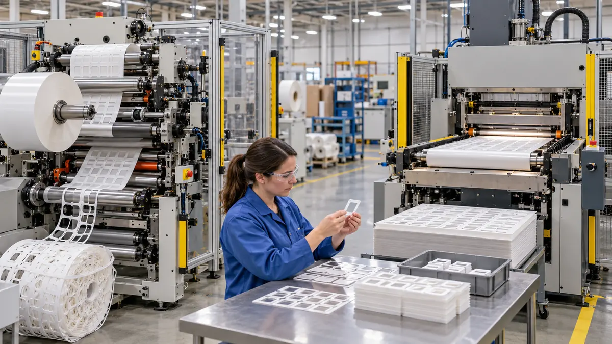
Rotary die cutting usually fits repeat, roll-fed production with stable geometry and higher throughput, while flatbed die cutting can suit development work, sheets, larger parts and flexible production volumes. The best process is the one that controls the released material stack, cut depth, tolerances, liner presentation and quality plan at the required volume—not simply the machine with the highest speed.
Quick Answer
Choose rotary die cutting when a roll-fed adhesive part needs repeat pitch, controlled orientation and sustained production rate. Choose flatbed die cutting when the program benefits from sheet handling, larger geometry, lower or variable quantities, or a different tooling and setup balance. Either process can make useful kiss-cut or full-cut parts; neither guarantees tolerance, clean release or automation readiness without a defined material stack and validation plan.
How Rotary and Flatbed Die Cutting Differ
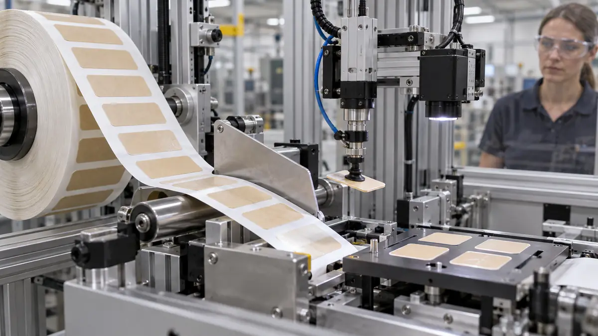
A rotary press brings a cylindrical cutting tool into contact with a continuously moving web. This architecture aligns naturally with rolls, fixed pitch, matrix removal and downstream rewinding or lamination. It can support efficient repeat production once the material path, tooling and register are stable.
A flatbed press brings a flat tool against material that pauses or indexes beneath it. It can process sheets or webs and may offer a practical setup for prototypes, lower quantities, large-format shapes or programs that change often. The exact capability depends on press size, tool design, registration, material handling and converter experience.
| Decision factor | Rotary die cutting | Flatbed die cutting |
|---|---|---|
| Material flow | Continuous or indexed roll-fed web | Indexed web or sheet handling |
| Typical production fit | Repeat work and higher sustained volume | Development, mixed work and flexible batches |
| Part presentation | Well suited to kiss-cut rolls at controlled pitch | Well suited to sheets and many custom layouts |
| Tool form | Cylindrical tooling matched to repeat geometry | Flat tooling matched to the press and sheet or web |
| Primary watchpoint | Tooling investment, register and web behavior | Cycle rate, sheet handling and press-area limits |
Select from Material, Geometry and Demand
Start with the adhesive stack
Transfer adhesive, film-carrier double-sided tape, foam, polyimide, PET, cloth, foil and laminated constructions cut differently. Adhesive flow, compressibility, backing toughness, liner thickness and total caliper affect tool clearance, edge quality and waste stripping. A process proven on thin film cannot be assumed to behave the same on soft foam.
Map critical geometry
Identify the features that control function: narrow webs, small holes, internal islands, corner radii, pull tabs, split liners and datum features. Separate critical tolerances from reference dimensions. Unrealistically tight limits can increase tooling and inspection cost without improving the assembly.
Use real volume and release strategy
Provide annual demand, batch size, release frequency, forecast stability and revision risk. A high annual total released in small changing batches may not favor the same process as one stable part run continuously. Include prototype needs and expected design changes rather than quoting only the mature-volume scenario.
| RFQ input | What to provide | Why it matters |
|---|---|---|
| Construction | Material codes, layers, liners, thicknesses and adhesive sides | Defines cut behavior and tool approach |
| Drawing | Dimensions, tolerances, radii, cut depth and datums | Defines functional geometry |
| Presentation | Individual, sheet, roll, pitch, orientation and core | Connects conversion to assembly |
| Demand | Prototype, batch and annual volume plus releases | Shapes setup, tooling and throughput economics |
| Quality | Sampling, edge limits, release behavior and traceability | Turns nominal parts into a controlled supply |
Design for Cutting, Matrix Removal and Placement
The same outline can behave differently depending on liner side, web direction and the waste that must be removed around it. Very narrow bridges may stretch or lift with the matrix. Sharp internal corners can create weak points or debris. Unsupported islands can stay with the waste instead of the finished part. Work with the converter to add practical radii, carrier bridges or alternative stripping sequences without changing the functional boundary.
For kiss-cut parts, define which layers are cut and which liner remains intact. For full-cut parts, define how pieces are counted, separated and protected. If automation will pick the part, specify pitch, orientation, optical contrast, peel plate behavior, release level, web tension, splices and maximum roll diameter. The delivery format is part of the component design.
Recommended Sourcing Workflow
- Define the function. State whether the part bonds, masks, insulates, seals, cushions or protects.
- Freeze the material stack. Identify every layer, liner and finished thickness.
- Release a controlled drawing. Mark critical dimensions, datums and cut-depth intent.
- Describe assembly. Include manual or automated pick, peel, align, pressure and takt time.
- Provide demand. Separate prototypes, validation lots and expected production releases.
- Review process options. Compare rotary, flatbed and any justified alternative.
- Approve tooling direction. Resolve radii, nesting, waste, pitch and revision control.
- Run production-intent samples. Use the nominated material and presentation format.
- Test the complete assembly. Verify placement, bond, function and environment.
- Lock change control. Define what requires notification and requalification.
Validate More Than Finished Dimensions
Measure critical features with a method suited to soft, adhesive and compressible materials. Excess contact pressure can distort a foam or transfer-adhesive part during inspection. Also inspect burrs, ragged backing, adhesive ooze, loose fibers, liner scoring and residual waste. Confirm that parts peel without curling, stretching or delaminating.
| Validation group | What to evaluate | Release evidence |
|---|---|---|
| Geometry | Critical profile, holes, apertures, pitch and registration | Drawing-based capability and sampling records |
| Cut quality | Edges, cut depth, burrs, liner damage and debris | Magnified inspection and approved limit samples |
| Web behavior | Matrix removal, splices, tracking, release and rewinding | Production-intent roll trial |
| Placement | Pick, peel, orientation, alignment, pressure and cycle time | Actual operator or equipment trial |
| Final function | Bond, seal, insulation, masking, aging or device performance | Product-owner qualification plan |
Compare Total Cost and Program Risk
Piece price can hide tooling, setup scrap, minimum run length, inspection, packaging, freight, inventory and revision exposure. A rotary route may become efficient at stable volume but carry more commitment if the geometry is still changing. A flatbed route may offer a practical bridge through prototypes and lower releases but have a different cycle-time structure.
Ask for a cost model at realistic batch quantities and include the effect on the assembly line. A part that costs slightly more but arrives on a reliable liner, peels cleanly and eliminates manual trimming may reduce total manufacturing cost. Conversely, expensive tight tolerances that do not protect function add risk without value.
Related Products and Articles
Frequently Asked Questions
Is rotary die cutting always more accurate than flatbed?
No. Accuracy depends on the press, tooling, material stack, register, environment, inspection method and converter process control. Compare actual capability for the released part.
Which process is better for prototypes?
Flatbed tooling may be practical for many development programs, but geometry, material and sample quantity determine the best route. Some prototypes may use another controlled process before production tooling is released.
Can both processes make kiss-cut parts?
Yes, depending on equipment and construction. The RFQ must define which layers are cut, liner condition, matrix removal and final presentation rather than using “kiss cut” as the complete specification.
When should a project move from flatbed to rotary?
Review the transition when geometry is stable and repeat volume, roll presentation or throughput justifies the rotary setup. Validate the transferred process instead of assuming parts are identical because the drawing is unchanged.
What files should be sent for a die-cut tape quotation?
Send a controlled drawing or CAD file, material stack, liner and cut-depth requirements, tolerances, presentation format, assembly method, batch and annual volume, quality plan and target schedule.
Choose a Die-Cutting Route from Production Evidence
Share the adhesive construction, drawing, critical features, cut-depth intent, liner, required part presentation, placement process, prototype quantity, batch releases and annual demand. JIAO TAO TAO can review rotary and flatbed converting routes and prepare production-intent samples for validation.
Discuss rotary or flatbed die cutting
Release Liners for Automated Double-Sided Tape Placement
Related Article

Need help choosing the right industrial tape?
Send us your application details, including temperature, surface material, size, quantity and current problem. Our team will help recommend a suitable tape material or custom die-cut solution.

simon@jiaotaotao.com


+86-136 1277 5969


+86-136 1277 5969
