
Industrial Double-Sided Tape for CNC Workholding Fixtures
Industrial Double-Sided Tape for CNC Workholding Fixtures
Industrial double-sided tape for CNC workholding can temporarily secure a thin, flat workpiece to a prepared fixture when conventional clamps would block the tool path. It is a process-specific holding method, not a universal substitute for mechanical fixturing. Cutting forces, part mass, tool path, adhesive area, surface condition, temperature, coolant, and backup containment must be assessed before machining.

Key Takeaways
- Use adhesive workholding only after engineering reviews cutting load, part escape risk, and machine safeguards.
- Maximize clean, flat bond area and minimize peel or prying loads at unsupported edges.
- Qualify the exact tape against fixture material, workpiece finish, coolant exposure, heat, and cycle time.
- Use locating stops and a controlled seating method so adhesive does not replace part location.
- Define removal and residue inspection before releasing the process to production.
When Adhesive Workholding May Fit
Thin plates, sheet components, engraving blanks, covers, and other flat parts can be difficult to clamp without obstructing a face-machining operation. Double-sided tape creates a low-profile bond between the part and a sacrificial fixture. The method is most credible when the workpiece has generous flat contact area, the cut is planned to limit lifting forces, and the fixture includes reliable location and containment.
Do not choose tape because a clamp is inconvenient. A released workholding plan must consider what happens if adhesion drops during the cut. Heavy parts, aggressive roughing, interrupted cuts, small adhesive area, warped stock, hot chips, and coolant exposure can make adhesive-only retention unsuitable. Mechanical stops, tabs, a frame, reduced cutting parameters, or a different fixture may be required.
Workholding Methods Compared
| Method | Potential advantage | Main limitation to review |
|---|---|---|
| Thin double-sided tape | Low profile and broad support for flat parts | Adhesive variability, removal, coolant, and part-release risk |
| Mechanical edge clamps | Direct retention and easy visual confirmation | Tool-path obstruction and local distortion |
| Vacuum fixture | Distributed holding with fast loading | Seal area, porosity, pump capacity, and through-cuts |
| Fixture adhesive or wax system | Conformal support for selected specialist processes | Heating, curing, cleanup, and process control |
| Tabs or sacrificial bridges | Positive material connection during profiling | Secondary removal and edge finishing |
Data Required for Tape and Fixture Selection
| Parameter | What to document | Why it matters |
|---|---|---|
| Workpiece | Material, dimensions, mass, flatness, finish, coatings, and allowable residue | Controls real contact area and removal risk |
| Fixture surface | Material, roughness, flatness, cleanliness, replaceable top plate, and locating features | Sets the second adhesive interface and setup repeatability |
| Machining plan | Tool type, engagement, depth, feed direction, entry, exit, through-cuts, and cycle time | Defines shear, peel, vibration, and thermal loads |
| Adhesive coverage | Strip layout, edge setback, gaps, holes, release tabs, and total bonded area | Determines support and where chips or fluid may enter |
| Environment | Dry or wet cutting, coolant type, mist, heat, chip flow, and dwell before cutting | Exposure may alter the adhesive or bond edge |
| Safety controls | Stops, containment, tool-path limits, first-off observation, and abort criteria | Reduces consequence if the workpiece shifts or releases |
Select Carrier and Thickness for Support
A thin PET-carrier tape can provide dimensional stability and controlled thickness on smooth surfaces. Tissue-carrier tape may conform more readily but can split during removal. Transfer adhesive produces a very thin bond line but can be harder to handle. Foam tape adds compliance, which may permit workpiece movement and should not be assumed suitable for precision machining.
Lay Out Adhesive to Resist the Expected Load
Place coverage beneath the load-bearing area rather than only around the perimeter. Keep tape clear of through-holes and cutter paths so adhesive does not contact the tool. Edge setback can reduce direct coolant attack and simplify trimming, but excessive setback leaves the workpiece unsupported. Engineering should release the pattern.
Separate Location From Retention
Use stops, pins, a pocket, or another datum to locate the workpiece before full seating. Sliding a part across exposed adhesive can trap debris, smear the bond, and create position error. A split liner or staged peel can preserve alignment until the workpiece touches the fixture at the intended location.
Controlled Setup, Machining, and Removal Workflow
- Release the workholding plan. Document the part, tape, coverage pattern, fixture, locating method, cutting strategy, and safety controls.
- Inspect both surfaces. Check flatness, burrs, oil, coolant film, oxide, coating damage, and embedded chips.
- Prepare by the approved method. Clean and dry the fixture and workpiece without introducing an unqualified residue.
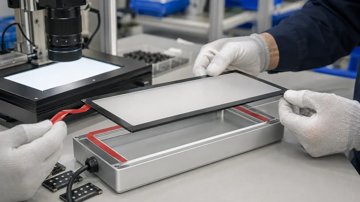
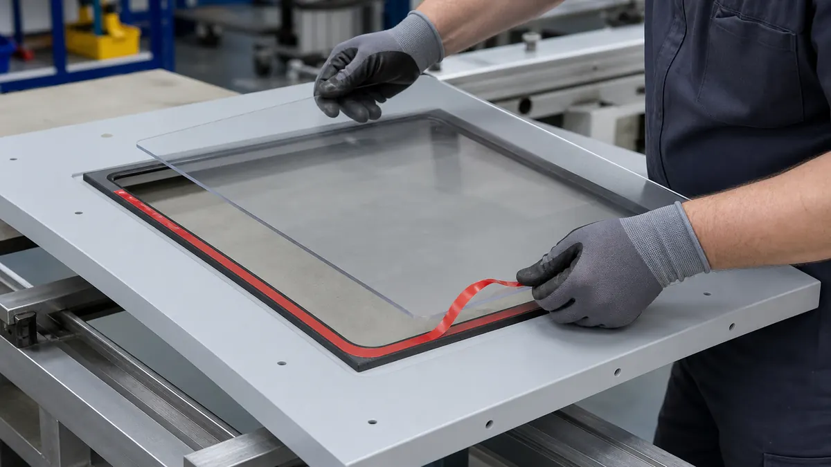
- Apply controlled tape strips. Avoid overlaps and wrinkles; roll or press each strip consistently and keep adhesive out of the tool path.
- Locate before full contact. Use stops or a staged liner, then apply the released seating pressure across the part.
- Observe dwell and verify setup. Confirm part location, edge contact, containment, and fixture clearance before closing the machine.
- Run a conservative first-off cycle. Follow the approved program and stop if the workpiece shifts, chatters, lifts, or generates unusual sound.
- Remove with a released method. Support the part, use the approved wedge or solvent only when qualified, and inspect both surfaces for residue or damage.
Common Problems and Corrective Directions
| Observed problem | Likely checks | Corrective direction |
|---|---|---|
| Part shifts during cutting | Low contact area, contamination, peel load, insufficient dwell, coolant ingress, or excessive cut | Stop the process; revise fixture, tape, coverage, and machining plan |
| Workpiece is not flat | Tape overlap, debris, warped stock, inconsistent thickness, or uneven seating | Remove and rebuild the setup with controlled surfaces and pressure |
| Edge lifts near a profile cut | Unsupported overhang, cutter exit force, weak perimeter contact, or fluid entry | Add support or containment and change tool path or coverage |
| Residue remains on the part | Incompatible finish, heat, long dwell, wrong adhesive, or removal angle | Screen another construction and qualify a cleanup method |
| Part bends during removal | High adhesion, thin section, prying from one point, or no release feature | Use a distributed removal method and redesign the liner or tape pattern |
Related Products and Articles
- Explore the industrial double-sided tape range for thin carrier and adhesive options.
- For controlled tape patterns, release tabs, and kiss-cut fixture sets, see custom die-cutting capabilities.
- Review the PE foam tape guide before using compliant foam constructions in any fixture.
- Send the part and fixture details for a material-screening discussion.
Frequently Asked Questions
Can double-sided tape safely hold a part during CNC machining?
It can be part of a qualified fixture for selected flat, low-risk operations. Engineering must review cutting forces, adhesive area, surfaces, environment, containment, and the consequence of release. Do not assume tape is safe for every part or tool path.
Which double-sided tape construction is best for CNC workholding?
The answer depends on surface finish, flatness, required bond-line thickness, cutting load, coolant, dwell, removal, and residue limits. Compare thin PET carrier, tissue carrier, and transfer adhesive on representative setups.
Can foam tape be used for precision machining fixtures?
Foam adds compliance and can permit motion under cutting load. Use it only when the responsible engineer has evaluated dimensional accuracy, load, compression, and containment for that specific process.
How should a taped workpiece be removed?
Use a released method that supports the part and distributes force. Avoid uncontrolled prying that can bend thin stock or damage the fixture. Qualify any solvent for the adhesive, metals, coatings, and workplace controls.
What information should an RFQ include?
Provide the workpiece and fixture materials, dimensions, mass, finishes, flatness, tape coverage drawing, cutting plan, coolant, dwell, required removal method, residue criteria, quantity, and safety constraints.
Plan a Controlled Workholding Trial
Share the part drawing, fixture surface, flatness, tape pattern, locating method, cutting sequence, coolant exposure, cycle time, removal method, and backup controls. JIAO TAO TAO can help shortlist an industrial double-sided tape format for engineering evaluation.
Industrial Double-Sided Tape for Air Filter Frame Assembly
Industrial Double-Sided Tape for Battery Pack Foam Pad Positioning
Related Article

Need help choosing the right industrial tape?
Send us your application details, including temperature, surface material, size, quantity and current problem. Our team will help recommend a suitable tape material or custom die-cut solution.

simon@jiaotaotao.com


+86-136 1277 5969


+86-136 1277 5969
