
Custom Die-Cut Tape for Smart Meter Display Window Bonding
Application Solutions · Meter Assembly
Custom Die-Cut Tape for Smart Meter Display Window Bonding
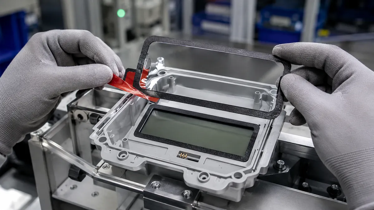
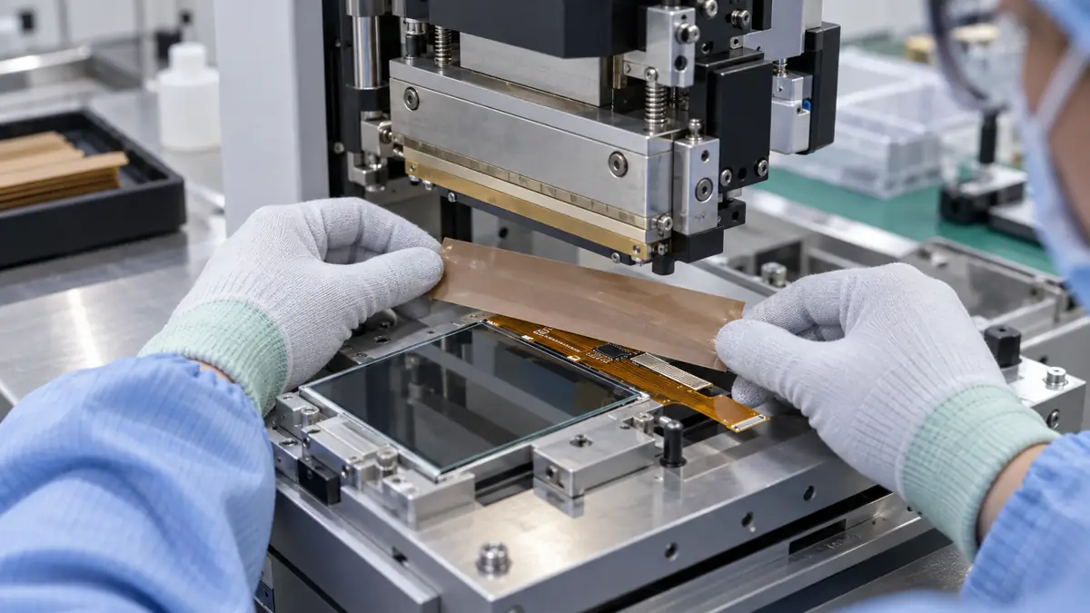
Custom die-cut tape for smart meter display window bonding can locate a clear lens, create a controlled bond line, keep adhesive outside the viewing aperture, and support the enclosure sealing design. The adhesive frame must be engineered around the actual lens, housing, display, gasket strategy, environment, assembly method, and service requirements.
Quick Answer
Choose a custom adhesive frame only after defining the smart meter lens and housing materials, coatings, aperture, curvature, flange width, surface energy, gasket or seal architecture, assembly temperature, installation pressure, display clearance, expected environment, and service method. Thin film tape can minimize bond-line height; conformable foam can accommodate a controlled gap. Neither option automatically creates a qualified environmental seal.
Define the Display Window Bonding Role
A smart meter front enclosure may combine a molded housing, clear lens, LCD or segmented display, light guides, labels, buttons, ports, fasteners, gaskets, and tamper-related features. The adhesive frame sits outside the viewing aperture and transfers load between the lens and housing flange. Its inner edge affects what users see; its outer edge can influence the enclosure’s moisture and dust path.
Tape should not cover the display active area, optical indicators, fastener bosses, snap features, ultrasonic-weld lands, gasket grooves, drainage paths, vents, or required inspection zones. If the lens is part of a safety, ingress, fire, impact, or utility-approval construction, the complete enclosure owner must define and validate those requirements.
| Interface | Design question | Critical boundary |
|---|---|---|
| Lens to adhesive | Is the surface glass, coated plastic, printed mask, or textured polymer? | Protect optics, coating, and visible edge appearance |
| Adhesive to housing | What resin, filler, texture, curvature, and flange width are present? | Maintain contact around the complete perimeter |
| Display keep-out | How much inner-edge tolerance can the aperture accept? | No adhesive, foam, or liner debris in the viewing area |
| Enclosure edge | How does the joint interact with gasket, drainage, fasteners, and service? | Do not claim sealing from tape alone |
Select the Adhesive Construction
Characterize both substrates
Identify the exact lens and housing materials, additives, coatings, inks, mold-release residues, surface textures, and allowed cleaning methods. Acrylic, polycarbonate, coated glass, ABS, PC blends, and lower-surface-energy plastics can require different adhesives or surface preparation. Use representative production parts rather than laboratory coupons alone.
Compare film and foam carriers
A thin PET-carrier double-sided tape supports a low, consistent bond line and precise conversion. A closed-cell foam construction can absorb a defined gap and distribute stress, but it increases height and can move under compression. Carrierless transfer adhesive offers another geometry option but needs careful liner and handling control.
Design for environment and service
Screen heat, cold, humidity, condensation, ultraviolet exposure where relevant, cleaners, oils, dust, vibration, enclosure flex, and lens movement. Consider whether the lens must be replaced without damaging the housing. Published tape data is a screening input, not proof of meter-level compliance.
| Selection input | What to document | Why it changes the choice |
|---|---|---|
| Lens | Material, coating, ink, size, thickness, flatness, optical zone | Controls adhesion, stress, appearance, and peel risk |
| Housing | Resin, filler, texture, flange, curvature, ribs, molding condition | Defines contact area and gap |
| Adhesive frame | Carrier, two adhesive sides, thickness, color, liner, tolerance | Controls joint height, handling, and visibility |
| Assembly process | Cleaning, treatment, temperature, pressure, datum, dwell, takt | Creates repeatable initial contact |
| Service duty | Indoor or outdoor, climate, fluids, vibration, life, repair | Sets representative qualification conditions |
Design the Die-Cut Frame and Liner
Build the die-cut drawing from stable housing and lens datums. Dimension the inner aperture, outer perimeter, corner radii, minimum frame width, indexing notch, split or kiss-cut liner, pull-tab position, and adhesive-free areas. Apply tolerance stack-up to the lens, housing, tape conversion, and placement process so the adhesive remains hidden without becoming too narrow to bond.
Use radiused internal corners where practical to reduce tearing and stress concentration. Avoid narrow unsupported webs that stretch when the liner is removed. A carrier liner can hold the frame square, while a split release liner may expose a small locating region before the full bond is committed. Package the parts to protect shape, cleanliness, and orientation.
Recommended Display Window Assembly Workflow
- Verify revisions. Match lens, housing, display, gasket, adhesive frame, and fixture.
- Inspect parts. Check flange flatness, molding defects, coating, ink, scratches, and contamination.
- Prepare as approved. Use only the released cleaning or treatment method and allow the surface to stabilize.
- Locate the first datum. Peel the defined liner section and register the frame without stretching it.
- Laminate progressively. Remove the remaining liner while applying controlled, even pressure.
- Align the lens. Use fixture stops or vision references and protect the optical surface.
- Apply final pressure. Seat the complete perimeter without bowing the lens or housing.
- Inspect and dwell. Check aperture, bubbles, edges, cosmetics, dimensions, and handling time.
Validate the Complete Meter Enclosure
Qualification should include representative material lots, minimum and maximum flange conditions, worst-case tolerance stacks, application temperatures, pressure limits, dwell times, and aged samples. Test the complete enclosure with its fasteners, gaskets, display components, labels, and housing stresses. Use the meter designer’s applicable safety and regulatory plan; do not infer compliance from an adhesive datasheet.
- Measure placement capability, aperture clearance, lens flushness, joint height, and cosmetic boundaries.
- Evaluate bond strength and failure mode after the defined dwell, temperature, humidity, condensation, UV, cleaner, vibration, impact, and enclosure-flex conditions as applicable.
- Run the released dust, water, pressure, thermal, electrical, optical, display-readability, and functional checks where required.
- Inspect for bubbles, edge lift, channel formation, adhesive squeeze-in, lens crazing, coating lift, fogging, and housing deformation.
- Requalify changes to resin, coating, lens, adhesive, thickness, die tool, liner, fixture, cleaning, pressure, or enclosure design.
Troubleshooting Window-Bonding Defects
| Observed issue | Check first | Corrective direction |
|---|---|---|
| Inner edge appears in the display | Aperture size, datum, tolerance stack, stretch, fixture | Recenter the geometry and improve placement control |
| Edge lifts at a corner | Radius, flange gap, texture, contamination, pressure, stress | Restore contact or revise the qualified frame design |
| Bubbles or channels remain | Lamination path, speed, pressure, dust, flatness, liner peel | Use progressive lamination and cleaner controlled surfaces |
| Lens cracks or crazes | Cleaner, stress, adhesive chemistry, clamp load, environment | Stop and review material compatibility and joint stress |
| Moisture enters the enclosure | Joint continuity, gasket interfaces, vents, fasteners, housing paths | Diagnose the full enclosure rather than adding tape blindly |
Related Products and Articles
Frequently Asked Questions
Can die-cut tape replace the meter enclosure gasket?
Not automatically. Bonding tape and gaskets may serve different structural and sealing functions. The complete enclosure must pass the owner’s applicable qualification plan.
Is foam tape better than thin film tape?
Foam can accommodate a controlled gap; film provides a thinner, more dimensionally stable bond line. Choose from the real substrates, flange, tolerance stack, environment, and joint requirements.
How is adhesive kept out of the viewing aperture?
Control the inner die-cut edge, corner radii, conversion tolerance, carrier liner, placement datum, fixture, and inspection limit as one system.
Can the lens be bonded immediately after molding?
Only if the released process accounts for part temperature, mold release, surface condition, dimensional stabilization, cleaning, and adhesive requirements.
What information belongs in a smart meter tape RFQ?
Provide lens and housing drawings, materials and coatings, flange and aperture tolerances, sealing architecture, environment, assembly method, quantity, packaging, and validation criteria.
Build a Controlled Smart Meter Lens-Bonding Trial
Share the lens and housing CAD, substrate details, display keep-out, flange geometry, gap map, gasket strategy, environment, assembly sequence, annual volume, packaging needs, and acceptance tests. JIAO TAO TAO can help shortlist adhesive constructions and die-cut liner formats for engineering trials.
Discuss display window bondingPET Silicone Tape for Enclosure Gasket-Land Masking
PET Silicone Tape for Wheel Hub Mounting Face Masking
Related Article
Need help choosing the right industrial tape?
Send us your application details, including temperature, surface material, size, quantity and current problem. Our team will help recommend a suitable tape material or custom die-cut solution.

simon@jiaotaotao.com


+86-136 1277 5969


+86-136 1277 5969
