
Custom Die-Cut Tape for Industrial Barcode Scanner Window Bonding
Application Solutions · Industrial Optical Devices
Custom Die-Cut Tape for Industrial Barcode Scanner Window Bonding
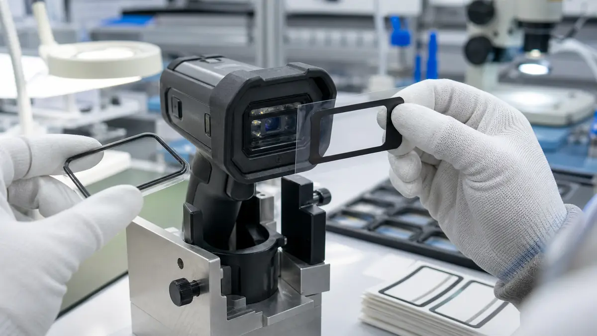
Custom die-cut tape for industrial barcode scanner window bonding can create a repeatable adhesive frame between a protective optical window and a scanner housing. The converted part must control the clear aperture, adhesive width, thickness, liner handling, contamination, and assembly datum without entering the optical path or compromising the device enclosure.
Quick Answer
Design the die-cut tape from the optical aperture and enclosure stack outward. Define the no-adhesive viewing zone, window overlap, minimum bond width, housing ledge, corner radii, vents or indicators, allowable squeeze-out, finished thickness, placement tolerance, and liner-removal sequence. Then qualify the exact window, coating, housing polymer, adhesive, and production process together.
Define What the Window Joint Must Do
An industrial barcode scanner may use a clear polycarbonate, acrylic, glass, or coated window to protect the imaging engine or laser optics. The adhesive frame can locate the window, retain it during handling, block selected stray light, and support an enclosure seal. These functions interact: a thicker foam may bridge housing variation but change window position, while a thin film adhesive can preserve the optical stack but demand better flatness.
| Joint function | Die-cut contribution | Key validation question |
|---|---|---|
| Window retention | Provides a continuous or segmented bond frame | Does it survive drop, vibration, impact, and aging? |
| Optical aperture | Creates a repeatable clear opening and light-control border | Does any edge enter the field of view or illumination path? |
| Environmental seal | Closes a designed perimeter interface | Are seams, corners, compression, and housing paths controlled? |
| Assembly location | Uses holes, tabs, asymmetric geometry, or kiss-cut carrier | Can operators or automation place it without rotation? |
| Cosmetic border | Hides the housing ledge when the design permits | Does color remain uniform without visible squeeze-out? |
Select Adhesive and Carrier for the Stack
Identify both bonding surfaces
Record the window material, hard coat, ink border, anti-reflective layer, texture, and cleanliness limits. Document the housing resin, paint, mold release history, glass reinforcement, texture, and flatness. Adhesion on a supplier plaque may not represent a molded scanner housing with real draft, ribs, and surface energy.
Choose thickness from gap and optics
A transfer adhesive creates a thin bond line, film carrier improves handling and dimensional stability, and foam can accommodate controlled gap variation. Thickness must not tilt the window, move it into a focal or illumination constraint, or create an exposed edge that collects dust.
Review temperature, chemicals, and light
Industrial scanners may encounter warehouse temperature cycles, cleaning agents, hand oils, UV exposure, humidity, and mechanical shock. The adhesive should retain the window without yellowing into the aperture, staining coatings, or losing edge seal. Use actual service and cleaning conditions in qualification.
| Selection input | What to define | Why it matters |
|---|---|---|
| Window | Material, coating, ink, thickness, edge finish, and curvature | Controls adhesion, optics, and stress |
| Housing | Polymer, coating, texture, flatness, ribs, and cleanliness | Controls wet-out and bond width |
| Adhesive format | Transfer, film carrier, foam, single layer, or laminated construction | Sets handling, thickness, and conformity |
| Environment | Temperature, humidity, UV, cleaners, oils, dust, and water exposure | Defines aging and sealing tests |
| Production | Manual or automated placement, pressure, dwell, fixture, and volume | Turns material data into process capability |
Design Aperture, Datums, and Liners
Build the die-cut drawing from released window and housing CAD plus the optical keep-out supplied by the device engineer. Tolerance the inner aperture, outer profile, corner radius, hole position, and adhesive web. Include variation from the tape converter, housing, window, fixture, and placement system.
An asymmetric tab or registration hole can prevent rotation. A split liner can expose only one side of the frame during alignment, and an extended pull tab can keep fingers away from the optical surface. Define whether the die cut is supplied as individual parts, sheets, rolls, or a carrier web; packaging must protect both cut edges and clean apertures.
Recommended Scanner-Window Assembly Workflow
- Verify revisions. Match housing, window, coating, die cut, fixture, and work instruction.
- Inspect parts. Reject chips, scratches, coating defects, warp, mold flash, and contamination.
- Clean as approved. Use only the validated cleaner, wipe, drying time, and environment.
- Load the housing fixture. Support the ledge without distorting the enclosure.
- Expose the first liner. Keep the remaining adhesive and clear window protected.
- Register the die cut. Use pins, ledges, vision marks, or an asymmetric carrier feature.
- Apply controlled pressure. Seat the full bond frame without stretching the part.
- Remove the final liner. Account for it and keep debris outside the aperture.
- Place the window. Lower it squarely from the specified datum and pressure pattern.
- Inspect immediately. Check aperture, squeeze-out, particles, edge seal, and window position.
Validate Optics, Bonding, and Enclosure Performance
Run the scanner’s complete functional test with representative minimum and maximum placement, window and housing tolerances, adhesive age, assembly pressure, and environmental conditioning. A visually acceptable bond can still change illumination, aiming, image contrast, focus, or decode performance.
- Measure die-cut and window position against released datums.
- Inspect particles, fibers, haze, bubbles, inner-edge lift, and adhesive squeeze-out under controlled lighting.
- Run barcode decoding across required symbologies, distances, angles, contrast levels, and illumination modes.
- Perform required drop, impact, vibration, thermal cycle, humidity, UV, cleaner, oil, dust, water, and enclosure tests.
- Evaluate bond strength and failure mode using product-owner methods rather than a generic peel value alone.
- Requalify changes to window, coating, housing resin, texture, adhesive, die geometry, liner, or assembly settings.
Troubleshooting Common Window-Bonding Defects
| Observed problem | Check first | Corrective direction |
|---|---|---|
| Adhesive visible in aperture | Inner-cut tolerance, placement datum, squeeze-out, and pressure | Increase the qualified keep-out or improve registration |
| Window lifts at corners | Corner radius, housing flatness, surface energy, pressure, and dwell | Match geometry and adhesive to the real ledge |
| Decode performance drops | Window position, haze, particles, reflection, light leak, and optical keep-out | Audit the complete optical stack |
| Dust appears after assembly | Cut edge, liner, static, packaging, wipes, and workstation control | Improve clean handling and converted-part protection |
| Seal test fails | Frame continuity, seams, vent path, compression, housing warp, and corners | Correct the enclosure and bond-frame design together |
Related Products and Articles
Frequently Asked Questions
Should the die-cut tape be transparent?
Not necessarily. A frame outside the optical aperture may be clear, white, gray, or black according to light-control and cosmetic requirements. No adhesive should enter the optical path unless the complete optical stack is designed for it.
Is foam tape better for a scanner window?
Foam can bridge controlled gaps, but it also adds thickness and can change window position or corner stress. Compare transfer, film-carrier, and foam constructions on the actual stack.
Can die-cut tape create a waterproof seal?
Only as part of a qualified enclosure design. Frame continuity, corners, housing paths, surface condition, compression, vents, and aging all affect sealing.
How can rotation errors be prevented?
Use asymmetric geometry, registration holes, a keyed carrier, printed orientation marks outside the part, fixture pins, or vision checks defined by the assembly process.
What information belongs in an RFQ?
Provide window and housing CAD, materials and coatings, optical keep-outs, thickness stack, environment, seal target, liner and packaging preference, placement process, volume, and validation plan.
Turn the Scanner-Window Joint into a Repeatable Part
Share the optical aperture, window and housing drawings, materials and coatings, bond-width limits, thickness stack, enclosure target, cleaning process, liner concept, placement tolerance, packaging, annual volume, and functional tests. JIAO TAO TAO can help prototype a die-cut adhesive frame for scanner assembly validation.
Discuss barcode scanner window bondingPET Silicone Tape for Cabinet Hinge Masking Before Powder Coating
Custom Die-Cut Tape for Power Electronics Thermal Pad Positioning
Related Article
Need help choosing the right industrial tape?
Send us your application details, including temperature, surface material, size, quantity and current problem. Our team will help recommend a suitable tape material or custom die-cut solution.

simon@jiaotaotao.com


+86-136 1277 5969


+86-136 1277 5969
