
Custom Die-Cut Tape for Automotive Rain-Light Sensor Pad Bonding
Application Solutions · Automotive Glass Electronics
Custom Die-Cut Tape for Automotive Rain-Light Sensor Pad Bonding
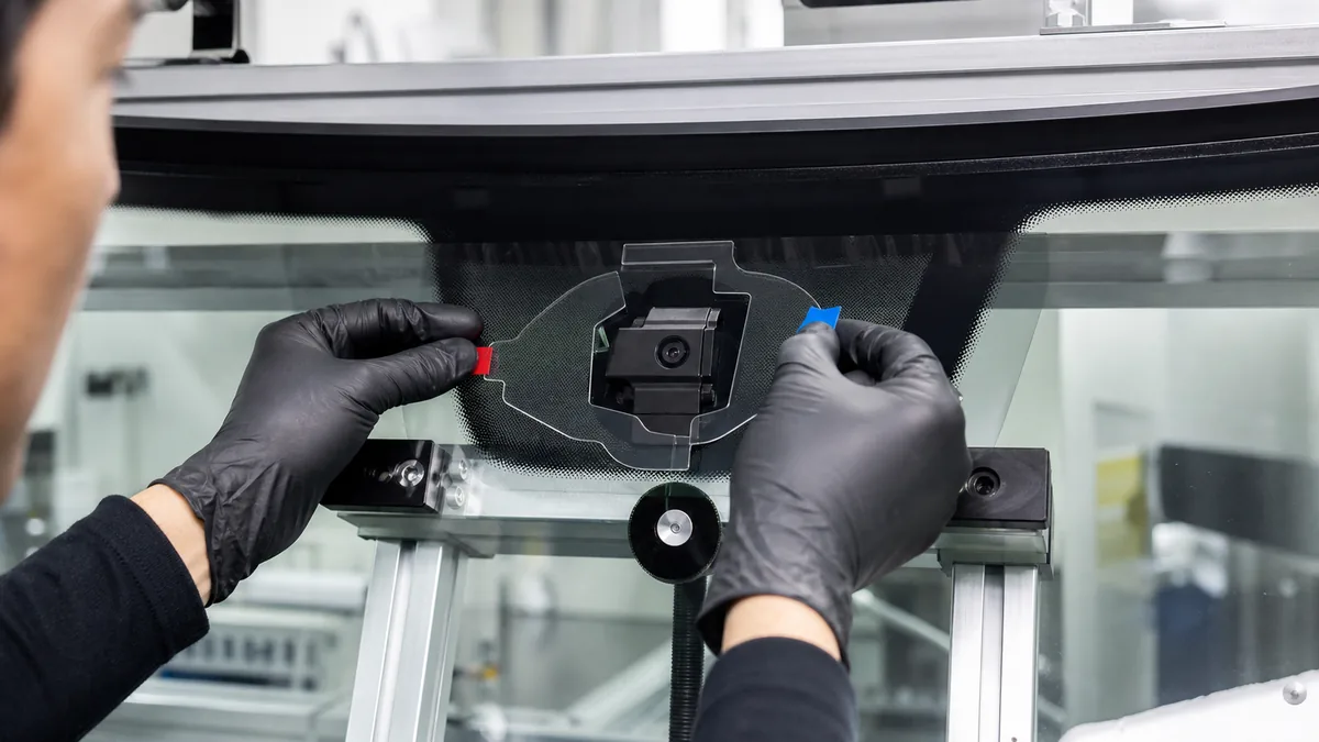
Custom die-cut tape for automotive rain-light sensor pad bonding must match the released optical interface, bracket, glass, liner, placement method, and environmental test plan. The converted pad is not a generic foam gasket: transparency, bubble control, thickness, cut geometry, cleanliness, and sensor function may all be critical.
Quick Answer
A rain-light sensor adhesive pad should be developed from the sensor supplier's released stack-up, not copied from a visible outline. Some designs use an optically functional transparent layer directly between the sensor and windshield; others bond a bracket or carrier while a separate gel or optical couplant serves the sensing zone. The drawing must identify which interface the die-cut tape belongs to.
What the Sensor Pad Must Control
Rain-light sensor assemblies detect conditions through the windshield and can include optical emitters and receivers, a transparent coupling area, housing, bracket, connector, trim cover, and cable route. The adhesive part may establish a consistent interface, register the module to a printed or ceramic zone, bond a carrier, control local thickness, or support installation before a secondary retainer engages.
The die cut must avoid active apertures and other keep-outs unless the specified material is intentionally part of the optical path. It also must accommodate windshield curvature, frit or coating boundaries, connector access, sensor orientation, and inspection from both sides of the glass.
| Interface zone | Possible requirement | Key question |
|---|---|---|
| Optical window | Transparent, bubble-free, uniform coupling | Is the adhesive itself approved for the optical path? |
| Bracket bond ring | Hold the carrier to glass around the sensing area | What load, cure, curvature, and keep-out apply? |
| Sensor housing pad | Locate or cushion the module in a retainer | Is the pad permanent, serviceable, or compressed? |
| Connector side | Provide clearance and assembly access | Can the operator install without stressing the harness? |
| Windshield decoration boundary | Control visibility and bond location | Which glass coating, frit, or primer is contacted? |
How to Select the Adhesive Construction
Separate optical and structural requirements
Optical transparency, refractive behavior, haze, and bubble tolerance require data and testing for the exact sensor design. Structural holding may prioritize adhesion to glass and the housing material, environmental durability, and stress distribution. A single converted part can serve both roles only when the complete construction has been designed and approved for them.
Match both substrates
Automotive glass may include coatings, ceramic frit, primer, or cleaning residues, while the sensor or bracket may be an engineering plastic, coated metal, elastomer, or transparent element. Record the exact contacted surfaces and their surface treatments. Evaluate cleaning and primer only within the released glass and sensor process.
Control thickness and conformity
A thin transfer adhesive creates little gap compensation. A clear compliant layer may follow slight curvature but can be more sensitive to handling, stretch, bubbles, and liner removal. Foam can distribute pressure or fill a gap in a bracket zone but is normally unsuitable in a direct optical path. Use the sensor stack-up to set nominal thickness and tolerance.
| Selection input | What to record | Why it matters |
|---|---|---|
| Pad function | Optical coupling, bracket bonding, positioning, cushioning, sealing, or service | Determines the material family |
| Substrates | Glass type, frit or coating, primer, sensor lens, plastic, or metal | Controls adhesion and compatibility |
| Optical requirement | Active area, transparency, haze, bubble, and sensor-signal criteria | Prevents use of an unapproved visible-zone material |
| Environment | Assembly temperature, heat, humidity, UV, cleaners, vibration, and aging | Defines the qualification sequence |
| Production method | Manual or automated placement, fixture, cycle time, inspection, and rework | Drives liner and presentation design |
Die-Cut Geometry, Tolerances, and Release Liner
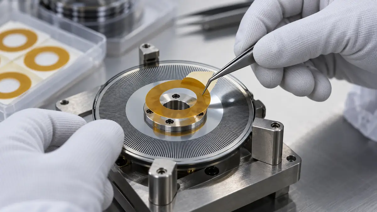
Build the converted-part drawing from released CAD and a measured stack-up. Mark the optical aperture, locating features, cable side, frit boundary, sensor outline, finger access, and any non-bonded pull tab. Asymmetry can prevent reversed placement. Rounded corners can reduce tear initiation, while split liners allow staged registration before the full adhesive area is exposed.
Specify cut quality as well as dimensions. Transparent materials can reveal edge particles, liner debris, scratches, stretch, and impressions. Packaging should protect the optical area and present parts in the correct orientation. For automated pick-and-place, define liner stiffness, pitch, web width, cavity orientation, and acceptable lift behavior.
Recommended Assembly Workflow
- Confirm the stack-up. Identify optical and non-optical adhesive zones, datums, thickness, and orientation.
- Verify incoming parts. Check windshield, sensor, bracket, pad revision, liner, packaging, and shelf controls.
- Prepare the environment. Use the released cleanliness, temperature, humidity, glove, and particle controls.
- Inspect both surfaces. Reject damage, dust, haze, residue, incorrect frit, or molding defects.
- Register the first surface. Use the fixture or visual datum without stretching the transparent pad.
- Peel in a controlled direction. Remove the split liner while preventing the exposed adhesive from folding or touching.
- Laminate progressively. Apply approved pressure from the first contact edge to displace air.
- Inspect the interface. Check bubbles, wrinkles, contamination, edge position, and full seating.
- Observe dwell or cure. Hold the assembly under the released time, temperature, and fixture condition.
- Run functional tests. Verify sensor response and required environmental or vehicle-level checks.
Qualification and Production Validation
Qualification should use the actual windshield construction, curvature, decoration, sensor, bracket, cable, fixture, and installation sequence. Include production variation in pad location, pressure, temperature, dwell, glass lots, and operator technique. Test before and after environmental conditioning; a clear interface at assembly is not proof of long-term function.
- Measure pad position, optical overlap, edge distance, thickness, and visible defects.
- Define bubble size, quantity, location, growth, and inspection lighting with the sensor owner.
- Verify sensor output across the approved operating and environmental range.
- Evaluate heat, humidity, UV where applicable, thermal cycling, vibration, cleaner exposure, and aging.
- Check bracket load, cable stress, trim fit, and service or replacement behavior when required.
- Maintain lot traceability and change control for adhesive, liner, glass, sensor, and process.
Troubleshooting Common Bonding Defects
| Observed issue | Check first | Corrective direction |
|---|---|---|
| Bubbles appear during lamination | Contact angle, pressure path, surface particles, pad stretch, and curvature | Revise staged placement and fixture support |
| Interface becomes hazy | Material revision, cleaner residue, moisture, heat, and chemical compatibility | Quarantine affected lots and repeat optical aging |
| Pad is misaligned | Datum, asymmetry, liner split, fixture, and operator view | Add keyed geometry or stronger registration features |
| Edge lifts from glass | Surface preparation, pressure, curvature, dwell, and adhesive match | Correct preparation and validate another construction if needed |
| Sensor function is inconsistent | Optical overlap, bubbles, thickness, sensor seating, connector, and calibration | Follow the sensor diagnostic plan; do not assume bond strength alone |
| Particles are visible | Slitting and die-cut cleanliness, liner debris, packaging, gloves, and station air | Strengthen clean handling and incoming inspection |
Related Products and Articles
Frequently Asked Questions
Can standard foam tape be used over the rain sensor optical window?
No, unless the released sensor design explicitly specifies that material. An optical interface requires a qualified transparent construction and functional testing.
Why use a custom die cut instead of trimming tape by hand?
A die cut can control the aperture, orientation, edge distance, liner tabs, and placement repeatability while reducing contamination and manual cutting beside the glass.
How are bubbles controlled?
Use clean surfaces, a stable fixture, staged liner removal, progressive contact from one edge, approved pressure, and defined inspection criteria. The exact method must match the pad and sensor design.
Should the pad be applied to the glass or sensor first?
Follow the released assembly sequence. The best first surface depends on the datum, curvature, liner design, pad handling, and how trapped air is displaced.
What belongs in an RFQ?
Provide the windshield and sensor CAD, pad function, optical keep-outs, substrates and treatments, thickness, tolerances, liner and packaging, assembly sequence, environmental exposure, volume, and validation requirements.
Define the Optical and Bonding Zones
Share the windshield and sensor stack-up, active optical area, substrates, curvature, pad function, thickness, die-cut drawing, liner concept, assembly method, expected volume, and qualification plan. JIAO TAO TAO can review a converted adhesive format for trials.
Discuss a rain-light sensor padPET Silicone Tape for Threaded Insert Masking During Powder Coating
PET Silicone Tape for Heat-Sink Mounting Face Masking
Related Article
Need help choosing the right industrial tape?
Send us your application details, including temperature, surface material, size, quantity and current problem. Our team will help recommend a suitable tape material or custom die-cut solution.

simon@jiaotaotao.com


+86-136 1277 5969


+86-136 1277 5969
