
Custom Die-Cut Tape for Parking Sensor Bracket Bonding
Application Solutions · Automotive Assembly
Custom Die-Cut Tape for Parking Sensor Bracket Bonding
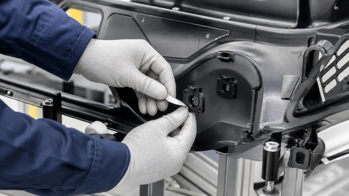
Custom die-cut tape for parking sensor bracket bonding can position and retain a molded bracket on the inner surface of an automotive bumper fascia. The adhesive part must keep the sensor aperture clear, match the actual plastics and surface preparation, support controlled placement, and remain one qualified element of the complete sensing assembly.
Quick Answer
Choose the adhesive die cut only after defining the bumper-fascia resin and surface, bracket material, bond flange, paint or molding process, sensor axis, acoustic field, installation sequence, temperature and chemical exposure, service method, and production takt. A thin adhesive ring can improve placement and distribute load around a compact bracket, but it cannot correct a distorted fascia, contaminated surface, incorrect sensor angle, weak bracket design, or an aperture outside tolerance.
Define the Bracket-Bonding Function
Ultrasonic parking sensors are mounted through small bumper apertures and rely on a controlled position relative to the visible fascia surface. The inner bracket may hold the sensor body, provide angular indexing, separate loads, and support service removal. Adhesive can bond the bracket flange to the fascia while eliminating liquid dispense variation, but it should not intrude into the aperture or alter the intended acoustic path.
Clarify whether the die cut is the primary bracket bond, a temporary locator before another fastening step, a gap-filling interface, or part of a hybrid joint. That decision controls carrier thickness, adhesive family, coverage, liner design, application pressure, dwell, and test plan.
| Assembly feature | Possible die-cut function | Engineering limit |
|---|---|---|
| Bracket flange | Distribute adhesive around the approved mounting perimeter | Flange stiffness and flatness still require control |
| Sensor aperture | Provide a precise central keep-out | No adhesive, liner, or debris may enter the sensing opening |
| Indexing feature | Orient the part to a pin, notch, or vision datum | Adhesive cannot compensate for a wrong molded angle |
| Local fascia contour | Conform within the qualified thickness and pressure window | Bridging and stored stress can reduce contact |
| Service interface | Support the released replacement sequence | Removal must not damage the fascia or sensor harness |
Select Adhesive and Carrier for the Real Plastics
Identify both substrates precisely
Bumper fascias and molded brackets can use different resins, fillers, surface textures, mold-release histories, coatings, and recycling content. Do not qualify against a generic “plastic” coupon. Record the approved material codes, molding conditions, surface side, age, texture, and any paint, primer, flame, plasma, or other preparation.
Balance conformability and dimensional control
A thin film-supported adhesive provides precise geometry but may not fill texture or contour. A foam carrier can improve contact over local variation while changing bracket height, compression, sensor axis, and long-term stress. Transfer adhesive offers low build but needs a stable liner and careful handling. Screen alternatives using the complete joint.
Review automotive exposure and assembly timing
Consider temperature cycling, humidity, water, road splash, cleaners, waxes, oils, vibration, impact, fascia flexing, and the delay between bonding and downstream handling. Define application temperature, surface preparation, pressure, dwell, and cure or wet-out time from qualified evidence rather than a generic rule.
| Selection input | What to document | Why it matters |
|---|---|---|
| Fascia substrate | Resin, filler, texture, coating, mold release, and curvature | Controls surface energy, contact, and stress |
| Bracket substrate | Resin or metal, flange flatness, ribs, and molded features | Defines the second bond interface and load path |
| Adhesive construction | Carrier, adhesive sides, thickness, liner, and lot | Controls gap fill, handling, and joint height |
| Assembly process | Cleaning, treatment, temperature, pressure, datum, and dwell | Creates repeatable initial contact |
| Vehicle duty | Climate, chemicals, vibration, fascia flex, wash, and service | Sets representative durability conditions |
Design the Adhesive Ring and Liner
Build the die-cut drawing from the bracket and fascia datums. Control the inner diameter, outer perimeter, width around fasteners or ribs, indexing notch, split or seam location, positional tolerance, and maximum adhesive encroachment toward the sensor aperture. Use radiused corners where practical and avoid narrow unsupported webs that distort during liner removal.
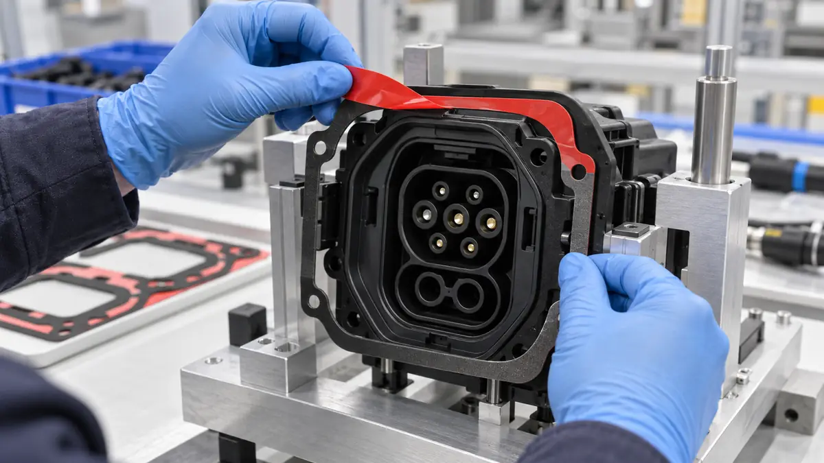
The liner is part of the production tool. A split liner can expose one section for pre-lamination to the bracket and protect the vehicle-side adhesive until final assembly. A pull tab can support gloved handling without touching the bond area. Define tab position so it does not fold under the bracket or interfere with the sensor and harness.
Recommended Bracket-Bonding Workflow
- Verify parts. Match fascia, bracket, sensor, die cut, liner, and work-instruction revisions.
- Inspect molded surfaces. Check aperture, contour, texture, damage, contamination, and flange flatness.
- Prepare only as approved. Use the released cleaner or treatment and observe its process window.
- Pre-laminate the die cut. Align to the bracket datum without stretching the ring or touching adhesive.
- Remove the final liner. Use the tab and confirm that no liner fragment remains on the part.
- Locate the bracket. Align to the aperture and angle datum before the adhesive makes full contact.
- Apply controlled pressure. Use the qualified fixture, force, area, and time around the complete flange.
- Inspect and protect dwell. Verify position, contact, keep-out, liner count, and handling delay.
Validate Bond, Alignment, and Sensor Function
Use production-molded fascias and brackets across approved material, texture, curvature, and dimensional ranges. Include normal and worst-case surface preparation, application temperature, operator or equipment, pressure, placement, dwell, and downstream handling. Test aged components where the process permits inventory before assembly.
- Measure bracket position, sensor axis, stand-off, aperture clearance, and visible exterior condition.
- Evaluate joint strength and failure mode with methods defined by the design owner after relevant conditioning.
- Run thermal cycling, humidity, water, chemicals, vibration, impact, fascia flexing, and vehicle-wash exposures in the approved sequence.
- Complete sensor diagnostic, detection, acoustic, rattle, false-trigger, and functional tests defined for the vehicle.
- Assess service removal and replacement without damaging the fascia, bracket, sensor, wiring, or adjacent finish.
Troubleshooting Parking-Sensor Bracket Bonds
| Observed problem | Check first | Corrective direction |
|---|---|---|
| Bracket shifts during dwell | Datum, fixture, initial tack, fascia curvature, pressure, and handling | Stabilize placement and the qualified handling window |
| Edge contact is incomplete | Flange flatness, texture, foam thickness, pressure coverage, and contamination | Correct the joint stack instead of adding local hand pressure |
| Adhesive encroaches into aperture | Inner diameter, die-cut distortion, placement, compression, and liner removal | Stop release and tighten geometry plus poka-yoke |
| Bond weakens after conditioning | Substrate lot, preparation, adhesive, dwell, temperature, water, and chemicals | Identify the failure interface and requalify the material system |
| Sensor gives false or weak response | Angle, depth, bracket stiffness, fascia, interference, harness, and aperture | Treat as a complete sensing-system issue, not only an adhesive issue |
Related Products and Articles
Frequently Asked Questions
Can a die-cut adhesive ring bond any parking sensor bracket?
No. The adhesive construction and geometry must match the actual fascia, bracket, contour, preparation, load, environment, sensor design, and production process.
Should adhesive cover the sensor aperture?
No. The opening and specified acoustic keep-out must remain clear unless the vehicle designer has released a different construction.
Is foam tape always better for a curved bumper?
No. Foam can improve conformity but also changes joint height, compression, stiffness, and sensor position. Compare film, transfer, and foam constructions in the complete assembly.
Why use a split liner?
A split liner can support accurate pre-lamination to the bracket and protect the vehicle-side adhesive until final placement. Its seam and tabs must be designed for the workstation.
What information belongs in an RFQ?
Provide the fascia and bracket materials and drawings, aperture and angle tolerances, surface preparation, joint thickness, liner needs, environment, service plan, quantity, and validation requirements.
Prepare a Parking-Sensor Bracket Bonding Trial
Share the fascia and bracket drawings, resin codes, surface texture, adhesive envelope, sensor-axis requirement, application fixture, pressure and dwell window, environmental duty, service method, production volume, and functional test plan. JIAO TAO TAO can help develop die-cut samples for controlled assembly trials.
Discuss parking-sensor bracket die cutsPET Silicone Tape for Wheel Hub Mounting Face Masking
PET Silicone Tape for Cabinet Hinge Masking Before Powder Coating
Related Article
Need help choosing the right industrial tape?
Send us your application details, including temperature, surface material, size, quantity and current problem. Our team will help recommend a suitable tape material or custom die-cut solution.

simon@jiaotaotao.com


+86-136 1277 5969


+86-136 1277 5969
