
Custom Die-Cut Tape for Camera Module Light Shielding
Custom Die-Cut Tape for Camera Module Light Shielding
Custom die-cut tape for camera module light shielding forms a controlled black barrier around lenses, sensor windows, flash openings, and compact optical housings. The part must block stray light without intruding into the optical path, contaminating the lens, lifting at narrow bridges, or shifting during downstream assembly. A successful design combines the correct opaque film or foam, adhesive, thickness, die-cut geometry, liner, and placement method.

Key Takeaways
- Optical performance depends on the complete stack, not simply on choosing a black material.
- The inner opening, bridge width, thickness, compression, and placement tolerance must be defined from the camera assembly.
- A stable liner and pick tab can make a small, fragile ring easier to handle without touching the adhesive.
- Approval should use the real lens, housing, cleaning process, assembly pressure, aging profile, and image-quality test.
Where Custom Die-Cut Tape Fits in a Camera Module
Compact camera and optical sensor assemblies place a lens, image sensor, housing, cover window, flash, and nearby electronics in a very small envelope. Reflections from internal walls, gaps, shiny fasteners, or adjacent light sources can enter the optical path. A die-cut black adhesive part can create a repeatable boundary around the required opening while also supporting local spacing, cushioning, dust control, or component retention when the selected construction is designed for those functions.
The part is not a substitute for optical design. Its role should be defined by the module engineer: block a specific light path, cover a reflective surface, separate adjacent optical channels, seal a housing interface, or hold a thin absorber in position. That definition determines whether the converted part should be a thin opaque film, a compliant black foam, an adhesive-backed cloth, or a laminated stack.
| Location or function | Typical die-cut format | Main design risk |
|---|---|---|
| Lens-barrel perimeter | Thin ring or frame with a controlled optical opening | Inner edge enters the field of view or shifts during assembly |
| Sensor or cover-window interface | Opaque frame or low-profile gasket | Particles, adhesive squeeze-out, or thickness variation affects the window |
| Flash and camera separation | Black divider, wall, or shaped foam gasket | Light leaks around corners or through compressed gaps |
| Housing seam | Closed-cell foam frame or film-and-foam laminate | Compression set, edge lift, or incomplete sealing |
| Reflective component cover | Small opaque patch with placement tab | Poor registration leaves a reflective edge exposed |
How to Select the Light-Shielding Material
Choose opacity and surface finish for the actual optical path
Black color alone does not prove that a material will control stray light. Evaluate transmission through the backing, reflection from the exposed surface, cut-edge behavior, and the way the material changes when stretched or compressed. A matte surface can reduce reflected light in some layouts, while a dense opaque film can provide a thinner barrier. Test the complete part under the wavelengths, angles, and illumination conditions used by the camera or sensor.
Match thickness and compliance to the gap
A thin film is useful when z-height is restricted and the part primarily covers or masks a surface. Foam can fill an uneven interface and maintain contact around a housing, but its compression changes the final thickness and may move the inner edge. Do not use nominal material thickness as the finished-stack value; include adhesive, laminated layers, release liners, compression, and production tolerances.
Confirm adhesive compatibility and cleanliness
The adhesive may contact engineering plastic, coated metal, glass, a flexible circuit, or another tape layer. Surface energy, mold release, cleaning chemistry, and texture all affect adhesion. Camera assemblies also require careful contamination control. Evaluate adhesive flow, volatile residue, particle generation, edge ooze, and removability according to the product’s own cleanliness and reliability plan rather than assuming that a general electronics tape is automatically suitable.
| Material option | Potential advantage | What to qualify |
|---|---|---|
| Black PET or other opaque film | Thin profile and precise die-cut edge | Optical density, reflection, curl, and adhesion at narrow bridges |
| Black double-sided film tape | Combines shielding geometry with two-surface bonding | Carrier opacity, total thickness, squeeze-out, and release sequence |
| Black closed-cell foam tape | Gap filling, local cushioning, and conformability | Compression range, recovery, dimensional stability, and inner-edge movement |
| Black cloth or nonwoven laminate | Conformability and low-gloss surface options | Lint, edge fray, thickness uniformity, and particle control |
| Multilayer converted stack | Combines shielding, spacing, and assembly functions | Layer registration, total tolerance, delamination, and cost |
Die-Cut Geometry and Liner Design
Define the opening from the optical keep-out zone
Start with a controlled drawing that shows the optical opening, lens-barrel datum, allowed adhesive land, keep-out zones, and maximum part shift. The inner cut is usually more critical than the outside profile. Include tolerance accumulation from the die cut, carrier liner, placement fixture, housing, and camera module. A theoretically perfect ring can still fail if the assembly datums do not control its final position.
Use bridges, radii, and tabs that survive handling
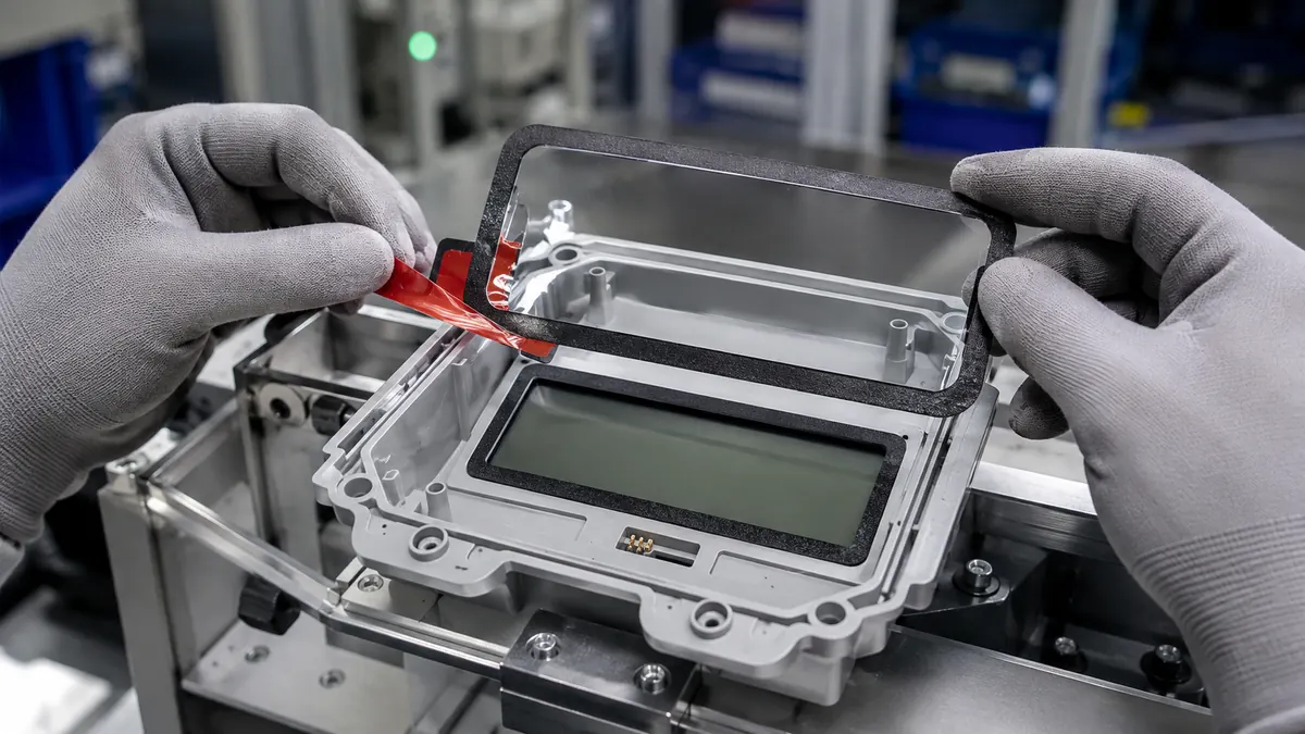
Very narrow corners and bridges can tear, curl, or remain in the waste matrix. Small inside radii may also be difficult to convert consistently. Where the design allows, use realistic corner radii and enough web width for the selected material. A nonfunctional pull tab outside the finished bond area can help operators or automation remove the part without contacting the adhesive or optical opening.
Engineer the release liner for placement
The liner controls more than storage. It affects flatness, part presentation, automatic feeding, static behavior, peel force, and the order in which adhesive surfaces are exposed. Kiss-cut parts can remain on a common sheet for manual placement, while individual pieces or rolls may suit automated assembly. Split liners, extended tabs, and differential release can simplify a two-step lamination sequence.
| RFQ input | Provide | Why it matters |
|---|---|---|
| 2D part drawing | Dimensions, datums, tolerances, radii, and keep-out zones | Defines the converted geometry and inspection plan |
| Optical requirement | Light source, wavelength range, angle, leakage criterion, and test method | Prevents material selection by color alone |
| Bonding surfaces | Material, coating, texture, cleanliness, and available bond width | Guides adhesive screening |
| Stack height | Nominal gap, compression, and maximum finished thickness | Separates film, foam, and laminate options |
| Assembly method | Manual, fixture-assisted, pick-and-place, roll lamination, or press | Determines liner and part presentation |
| Reliability profile | Temperature, humidity, chemicals, vibration, drop, and aging sequence | Defines production-representative qualification |
| Quality criteria | Registration, particle, edge lift, appearance, and optical limits | Creates measurable acceptance conditions |
Recommended Application and Validation Workflow
- Verify the part and orientation. Confirm material code, revision, adhesive side, optical opening, and liner-removal sequence.
- Prepare the workstation. Follow the assembly owner’s ESD, particle, and cleaning controls for the camera module.
- Locate from defined datums. Use housing pins, a nest, or machine vision rather than aligning only by eye to the lens image.
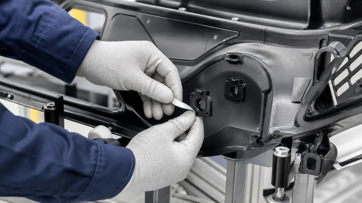
- Remove the liner without distorting the part. Peel the liner back at a controlled angle and avoid stretching narrow bridges.
- Place once and apply uniform pressure. Use a specified roller, pad, or press fixture that does not contact the optical window.
- Inspect the inner edge and bond land. Check registration, wrinkles, trapped particles, edge lift, exposed adhesive, and intrusion into the keep-out zone.
- Test optical performance. Run the defined dark-frame, flare, ghosting, crosstalk, or leakage inspection for the actual module.
- Complete reliability testing. Recheck adhesion, geometry, and image performance after the required environmental and mechanical sequence.
Troubleshooting Common Defects
| Observed issue | Part checks | Process checks |
|---|---|---|
| Light leak remains at one corner | Opacity, corner radius, gap fill, inner profile, and foam compression | Placement datum, housing flatness, and press uniformity |
| Ring shifts toward the lens | Adhesive tack, liner release, bridge width, and dimensional stability | Fixture clearance, placement speed, and pressure direction |
| Edge lifts after aging | Adhesive compatibility, bond width, curl, and surface treatment | Cleaning, dwell before test, temperature, and humidity sequence |
| Particles appear near the window | Cut-edge debris, liner contamination, cloth lint, and waste removal | Workstation cleanliness, handling, and inspection timing |
| Adhesive enters the optical opening | Adhesive coat weight, inner cut, compression, and squeeze-out margin | Press load, temperature, and alignment |
Related Products and Articles
- Review custom die-cutting capabilities for high-temperature, double-sided, foam, and insulation materials.
- See how custom die-cut tape is specified for LED optical and housing assemblies.
- Compare industrial double-sided tape constructions when the part must also bond two surfaces.
- Send the camera-module drawing and optical keep-out requirements for a material-format review.
Frequently Asked Questions
What material is best for camera module light shielding?
There is no universal best material. Thin opaque film suits low-profile masking, while black foam can fill a controlled gap. The choice depends on optical density, reflection, thickness, compression, cleanliness, adhesive compatibility, and the module’s reliability profile.
Can a die-cut gasket both block light and seal against dust?
It can support both functions if the material, cell structure, compression, joint continuity, and cleanliness are designed for them. The optical and particulate acceptance tests should be defined separately because a part that blocks light is not automatically a qualified dust seal.
How close can the die-cut edge be to the camera lens?
The distance must come from the optical keep-out zone plus the accumulated tolerance of the part and assembly. Include die-cut accuracy, placement variation, housing position, compression, and environmental movement rather than using a generic clearance.
Should camera light-shielding parts be supplied on sheets or rolls?
Sheets can simplify manual placement and low-volume builds. Rolls may support automatic feeding and high-volume conversion. Part size, liner stiffness, pitch, orientation, static control, and the placement equipment determine the better format.
What should be checked during sample approval?
Check registration, inner-edge geometry, opacity, reflection, adhesion, compression, particles, adhesive flow, assembly handling, optical image performance, and results after the complete reliability sequence. Use the real camera stack and production process.
Request a Camera Module Die-Cut Tape Review
Share the 2D drawing, optical keep-out zone, bonding surfaces, finished thickness, light-leak test, assembly method, environmental profile, annual volume, and preferred sheet or roll format. JIAO TAO TAO can help shortlist an opaque film, foam, or laminated die-cut construction for your own validation.
Contact the technical team with your camera-module requirements.
PTFE Tape for VFFS Machine Sealing Jaws
PTFE Tape for PVC Window Profile Welding Machines
Related Article
Need help choosing the right industrial tape?
Send us your application details, including temperature, surface material, size, quantity and current problem. Our team will help recommend a suitable tape material or custom die-cut solution.

simon@jiaotaotao.com


+86-136 1277 5969


+86-136 1277 5969
