
Custom Die-Cut Tape for LED Lighting Assembly
Custom Die-Cut Tape for LED Lighting Assembly
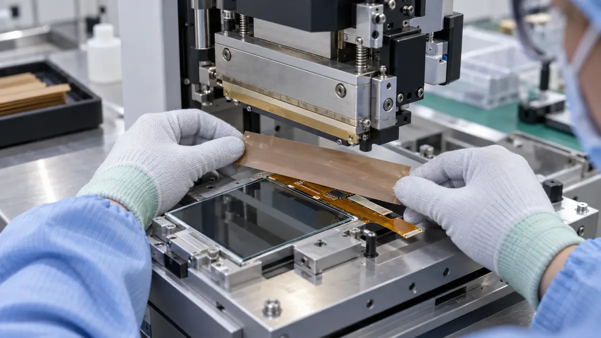
Custom die-cut tape for LED lighting assembly converts adhesive films, foams or double-sided materials into ready-to-place rings, gaskets, pads and insulation parts. It is useful when operators need repeatable alignment around lenses, boards, housings or cable exits and manual trimming would slow the line. The correct part must match the LED product’s surfaces, geometry, heat path, optical zone and assembly method; a drawing alone is not enough. This guide is for LED product engineers, sourcing teams and assembly planners preparing an application-specific RFQ.
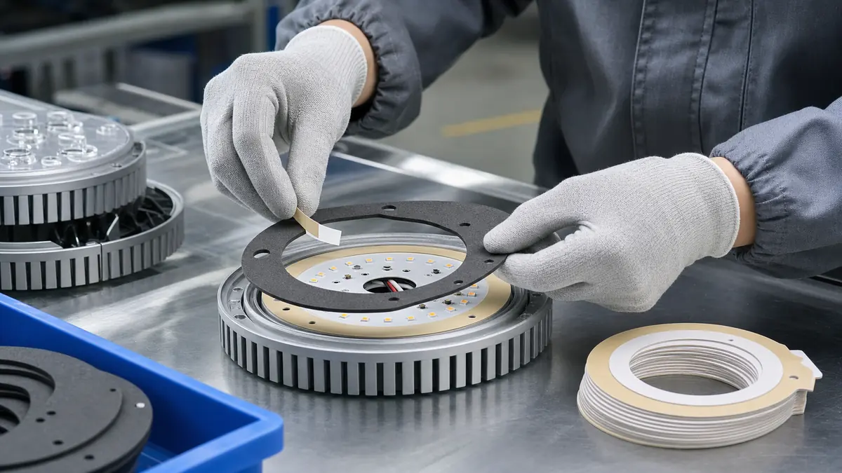
Where Die-Cut Adhesive Parts Fit in an LED Assembly
LED luminaires combine metal heat sinks, coated housings, printed circuit boards, lenses, diffusers, wiring and seals. Different locations therefore need different adhesive constructions. A thin film ring may hold a lightweight optical component, while a foam gasket may fill a controlled gap or reduce vibration. A shaped insulation film can separate a conductor from a metal housing, and a pull-tabbed masking part can protect a local area during coating or assembly.
Do not treat every shaped adhesive as a thermal interface material. A general bonding tape can add thermal resistance if it sits in the heat path. The LED thermal design team should define whether the part is for bonding, sealing, cushioning, masking or insulation before samples are made.
Specification Table for an RFQ
| Parameter | Information to Provide | Assembly Impact |
|---|---|---|
| Function | Bonding, gasketing, cushioning, masking or insulation | Determines the material family and qualification plan |
| Contact surfaces | Aluminum, paint, plastic, PCB coating, glass or diffuser material | Adhesion varies with surface energy, texture and contamination |
| Geometry | 2D drawing, tolerances, holes, slots, corners and keep-out zones | Controls fit, tool design and placement repeatability |
| Thickness | Available gap, compression target and bondline limit | Affects sealing, optical alignment and housing closure |
| Thermal exposure | Measured local temperature, cycles and service duration | Influences adhesive aging and dimensional stability |
| Delivery format | Individual parts, sheets, roll format, pitch and liner tab | Must match manual or automated placement |
Choose the Material by Function
Thin film parts for insulation or precise placement
PET and polyimide films can be converted into thin shapes when the assembly needs defined edges and low build. Selection depends on the required electrical role, temperature profile, stiffness and adhesive system. If the part is a permanent electrical-insulation component, verify the exact material data and the completed device design rather than relying on the generic film name.
Foam gaskets for controlled gap filling
Foam-backed parts can accommodate surface variation and provide cushioning or sealing. Engineers should define compression, recovery, cell structure, thickness tolerance and the effect of long-term load. Too much compression can distort an optical stack; too little can leave an incomplete seal.
Double-sided parts for lightweight component bonding
Thin double-sided constructions may bond labels, reflectors, trim or other lightweight elements away from the primary heat path. Adhesive choice should be screened on the actual coated aluminum and plastic grades because mold release, paint texture and cleaning residues can change bond behavior.
Design the Geometry for Reliable Placement
- Use datum holes, asymmetric shapes or a keyed corner to prevent reversed placement.
- Keep adhesive clear of LEDs, lenses, vents, fasteners and electrical contacts.
- Add a liner pull tab where gloves or automated grippers must remove the release liner.
- Use suitable corner radii instead of unnecessarily sharp internal corners.
- Define whether the drawing dimension refers to the adhesive, liner or finished laminate.
- Set tolerances from the assembly need, then confirm that the converting method can hold them.
Rotary, Flatbed and Laser Converting Compared
| Method | Typical Strength | Questions to Confirm |
|---|---|---|
| Rotary die cutting | Repeatable roll-fed production and controlled pitch | Tooling, web direction, liner, part spacing and expected volume |
| Flatbed die cutting | Flexible sheet processing and many shaped parts | Sheet layout, nesting, part removal and batch size |
| Laser cutting | Fast geometry changes for selected materials and prototypes | Edge condition, heat effect, residue and material compatibility |
The converting process should be selected after material and part-function review. A rapid prototype method does not automatically represent the edge quality or delivery format of the volume process.
Prototype and Production Validation
- Clean production parts with the approved process and record surface condition.
- Apply prototypes using the intended pressure, fixture and dwell time.
- Check placement, housing closure, lens alignment and any adhesive squeeze-out.
- Run the required thermal cycles, humidity or vibration checks for the luminaire design.
- Inspect lift, creep, foam compression set, liner behavior and material migration.
- Approve the drawing, material code, liner, packaging and revision before volume production.
FAQ
Which die-cut tape is best for an LED light?
There is no single best construction. Choose by function, contact surfaces, local temperature, gap, optical keep-out zones and service conditions. Test the exact adhesive part in the completed assembly.
Can die-cut foam tape be used as a thermal pad?
Not unless the specified construction is designed and documented for thermal transfer. General foam adhesive is normally evaluated for bonding, cushioning or sealing and may interrupt a heat path.
What files are needed for a custom die-cut quotation?
Provide a dimensioned drawing, material or performance requirements, surface details, thickness, tolerance, liner format, quantity and application process. A physical sample can help when the geometry is difficult to describe.
Can the parts be supplied for automated placement?
Yes, selected shapes can be supplied on a roll or carrier, but pitch, orientation, liner stiffness, release force and vision-system requirements must be defined with the converting supplier.
Related Products and Articles
- Die-cut and customized adhesive tape solutions
- Die-cut adhesive foam tape product example
- Custom die-cut tape for precision assembly
Request a Prototype Die-Cut Part
To evaluate custom die-cut tape for LED lighting assembly, send JIAO TAO TAO your drawing, part function, substrates, local temperature profile, thickness limit, liner format and target volume. The technical team can help narrow the material and converting route for prototype validation. Contact the technical sales team.
PTFE Tape for Blister Packaging Heat-Seal Plates
PTFE Tape for Composite Mold Release Surfaces
Related Article
Need help choosing the right industrial tape?
Send us your application details, including temperature, surface material, size, quantity and current problem. Our team will help recommend a suitable tape material or custom die-cut solution.

simon@jiaotaotao.com


+86-136 1277 5969


+86-136 1277 5969
