
Custom Die-Cut Tape Pull Tabs and Split Liner Design
Industrial Tape Application Guide
Custom Die-Cut Tape Pull Tabs and Split Liner Design
Design custom die-cut tape pull tabs and split liners around peel direction, operator access, liner release, placement datum and assembly validation.
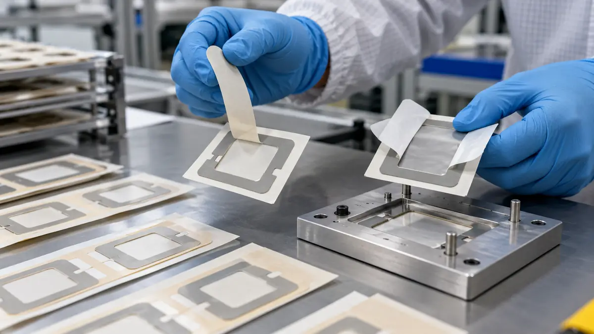
Quick Answer: Design the Peel Before the Part
Custom die-cut tape pull tabs and split liners should be designed from the real assembly sequence: which side bonds first, what the operator or gripper can reach, where the part is supported, how the liner peels and which datum controls placement. This guide is for product designers, manufacturing engineers and buyers whose adhesive parts are difficult to pick, peel or place. A tab is useful only when it preserves the adhesive geometry and improves repeatability.
Start with a video or direct observation of the current assembly. Record glove type, access, peel direction, fixture, first-bond substrate, placement tolerance and failure modes. A converter cannot optimize liner architecture from a finished-part outline alone. Technical content reviewed: .
Define What Each Liner Must Do
A release liner protects adhesive during converting, transport and handling. It can also carry small parts in an indexed array, control flatness, support a fragile frame, expose only one zone at a time or provide a non-adhesive grip. These functions may require different paper or film stiffness, release levels and cut patterns on the two sides.
| Liner function | Design question | Failure if undefined |
|---|---|---|
| Protect adhesive | Which face remains covered until final assembly? | Contamination, blocking or premature exposure |
| Carry the part | Sheet, roll, island or individual presentation? | Parts move, curl or cannot feed |
| Enable pickup | Where can fingers, tweezers, vacuum or a robot reach? | Edge picking, adhesive touch or distorted parts |
| Stage bonding | Must one section expose before another? | Trapped air, misalignment or early contact |
| Preserve datum | Which liner edge, hole or carrier feature locates the part? | Tab improves peeling but placement still varies |
Compare Pull Tabs, Split Liners and Extended Carriers
Integral pull tab
An integral pull tab is a liner area without adhesive under the grip zone. It may be created by kiss cutting and matrix removal or by a deliberate liner overhang. It gives the operator a positive start point, but the tab must not interfere with the product, fixture or package.
Split or scored liner
A split liner divides removal into controlled stages. It can expose a central locating strip first or allow one half to bond while the other remains protected. The split must not cut into adhesive, shed debris or create a ridge that distorts a thin part.
Secondary tabbing tape or extended carrier
Where geometry or volume makes an integral tab impractical, a separate tabbing material or extended common carrier may provide access. This adds materials and process steps, so bond to the liner, tab placement and storage must be validated.
| Option | Useful when | Primary risk |
|---|---|---|
| Integral dry-edge tab | Manual removal needs a clear grip | Tab too small, weak or positioned against an obstruction |
| Center split liner | Part is aligned first, then bonded outward | Split damages adhesive or creates an uncontrolled hinge |
| Offset split liner | One edge or datum must bond first | Asymmetric peel distorts a narrow frame |
| Common carrier sheet | Many small parts need indexed handling | Part release and pitch vary across the sheet |
| Roll-fed kiss-cut array | Semi-automatic or automatic placement | Winding direction, pitch, matrix and release mismatch equipment |
Create a Converter Drawing That Includes Handling
The drawing should identify the adhesive part, top and bottom liners, cut depths, tab region, split line, carrier outline, pitch, orientation and first-bond face. Add functional datums and critical-to-quality dimensions. Avoid calling every cut “die cut”; distinguish through-cut, kiss-cut, score, perforation and liner-only cut.
Specify sequence, not only geometry
Use numbered notes or a simple cross-section to show: remove carrier liner, locate part, apply pressure, remove secondary liner, complete the bond. Define whether matrix remains, which waste is removed by the converter, and how exposed adhesive is protected. State the packaging orientation so the first usable part is obvious.
| Drawing item | Required definition | Why it matters |
|---|---|---|
| Layer stack | Adhesive, carrier, top liner, bottom liner and any laminate | Prevents reversed or incomplete constructions |
| Cut map | Cut depth and tolerance for every contour or split | Protects liners and adhesive faces |
| Handling feature | Tab size/location, split position and peel direction | Connects geometry to the assembly motion |
| Presentation | Roll/sheet/piece, pitch, gap, core, winding and orientation | Controls workstation or equipment compatibility |
| Quality plan | Dimensions, release behavior, cleanliness and sampling | Defines acceptance beyond shape alone |
Illustrative Assembly-Time Screen
Use a short observation study to decide whether a tab or split deserves a prototype. Measure liner-start time, peel time, placement time, rework and damaged parts separately. Do not claim savings from one experienced operator or a single perfect part.
Protect quality metrics beside time
Track touched adhesive, stretched frames, liner fragments, folds, trapped air, misplacement and rework. A faster peel that doubles handling damage is not an improvement. Include operators with the actual gloves and reach constraints, plus the intended fixture or automation.
Prototype the Part and Assembly Together
- Map the current task. Record first-bond face, access, datum, peel direction, pressure tool and inspection.
- Freeze the adhesive material. Separate material performance from liner-design changes where possible.
- Create two or three concepts. Compare no tab, integral tab and a split-liner sequence rather than optimizing one idea blindly.
- Review the cut stack. Confirm which layers each cut reaches and where waste is removed.
- Build representative samples. Use intended liner, adhesive, part size, pitch and packaging.
- Condition samples. Include storage, transport, temperature and humidity states required by the project.
- Run real assembly trials. Use multiple operators or equipment states and actual substrates.
- Measure time and defects. Keep peel-start, placement, rework and damage data separate.
- Test the finished bond. Complete pressure, dwell, environmental and functional validation.
- Release the drawing. Lock material codes, cut depths, dimensions, presentation and change-control requirements.
Validate Liner Release, Placement and Final Bond
Release force must be high enough to protect the part through converting and transport yet low and stable enough for the intended peel motion. Evaluate the full stack after aging because liner release, adhesive flow and part stiffness can change. For automated pickup, verify pitch, curl, carrier flatness, sensor visibility and peel-plate behavior.
Keep liner convenience separate from bond performance
A tab changes handling, not the fundamental compatibility of the adhesive with the substrates. Surface preparation, pressure, dwell, temperature, environment and joint design still require their own validation. Use the same finished-bond tests for tabbed and non-tabbed samples.
| Validation group | Check | Release evidence |
|---|---|---|
| Converting | Cut depth, burr, matrix removal, debris and part dimensions | First article and capability results |
| Packaging | Flatness, blocking, tab damage, orientation and count | Conditioned pack inspection |
| Peeling | Start access, release consistency, part distortion and fragments | Multi-user or equipment trial |
| Placement | Datum, tolerance, air entrapment, touch contamination and pressure | Assembly capability evidence |
| Final bond | Environmental, mechanical and functional requirements | Released product validation |
Troubleshoot Pull-Tab and Split-Liner Failures
| Symptom | Check first | Controlled improvement | Revalidation |
|---|---|---|---|
| Tab tears off | Tab geometry, liner strength, cut depth and peel direction | Increase supported grip area or correct cut stack | Conditioned peel trials |
| Adhesive part lifts with liner | Release balance, carrier support, die-cut edge and peel angle | Adjust liner/release architecture with the converter | Part transfer and placement capability |
| Split liner leaves fragments | Score depth, liner fibers, radius and handling | Revise liner material or cut method | Cleanliness and full peel sequence |
| Frame stretches during peel | Narrow sections, adhesive stiffness, tab location and support | Move the split/tab or retain more carrier support | Dimensions after placement and final fit |
| Operator still touches adhesive | Access, glove size, fixture, peel order and tab visibility | Redesign the interaction, not only the tab length | Multi-operator contamination and defect study |
Related Products, Articles and Technical Sources
Technical process references
Strouse's kiss-cutting guide explains cutting the adhesive construction while leaving the liner intact and shows a tab created through controlled cut depth. CGR Products' pull-tab and split-liner guide describes integral tabs and secondary tabbing approaches for assembly handling. 3M's heat-debondable tape process guide notes that die-cut construction and easy-liner side should follow the application process. These are source-specific process references, not guaranteed dimensions for a new part.
Frequently Asked Questions and RFQ Checklist
What is a pull tab on a die-cut adhesive part?
It is a non-adhesive grip area or attached tab that helps start liner removal without touching the bond surface.
When is a split liner better than one full liner?
Use it when staged exposure improves alignment, air release or handling, provided the split does not damage the adhesive or part.
Can tab size be standardized across all parts?
No. Access, glove use, part stiffness, liner strength, packaging and peel direction change the required geometry.
Does an easier liner improve bond strength?
Not by itself. It may reduce contamination and placement errors, but the adhesive, surfaces, pressure, dwell and environment still control bond performance.
What belongs in a die-cut liner RFQ?
Provide the layer stack, part drawing, substrates, assembly sequence, first-bond face, tab/split concept, cut depths, tolerance, presentation, volume and validation plan.
Design the Adhesive Part Around the Assembly
Share the material stack, CAD drawing, first-bond face, peel sequence, datum, fixture, packaging, annual volume and current handling defects. JIAO TAO TAO can prepare tab and split-liner prototypes for controlled trials.
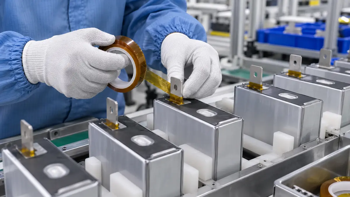
Polyimide Tape for Lithium Battery Tab Root Insulation
Related Article
Need help choosing the right industrial tape?
Send us your application details, including temperature, surface material, size, quantity and current problem. Our team will help recommend a suitable tape material or custom die-cut solution.

simon@jiaotaotao.com


+86-136 1277 5969


+86-136 1277 5969
