
Release Liners for Automated Double-Sided Tape Placement
Buying Guides · Automated Converting
Release Liners for Automated Double-Sided Tape Placement
A double-sided tape release liner for automation must present each converted part consistently to the feeder, peel plate, vision system and pickup tool. Liner stiffness, release balance, flatness, splice design and part pitch should be specified with the adhesive construction and placement cell—not chosen as packaging details after the die cut is finished.

Quick Answer
Treat the release liner as a functional machine component. First define how the roll unwinds, how the web is guided, where the liner bends, how the part separates, what the pickup tool contacts and how the empty liner is collected. Then select the liner and release system with the exact double-sided adhesive, die-cut geometry and equipment speed. A liner that works for hand peeling may curl, tear or release unpredictably in a small-radius automated path.
Map the Placement Cell Before Quoting
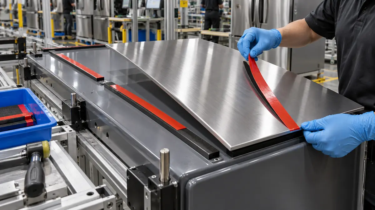
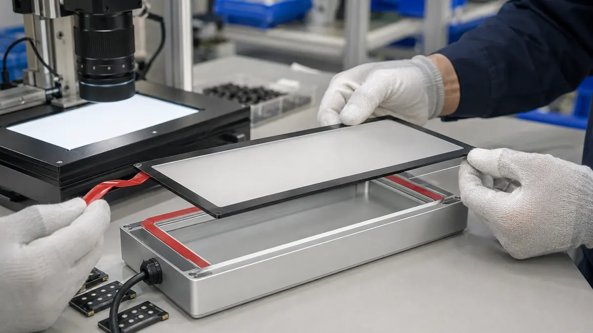
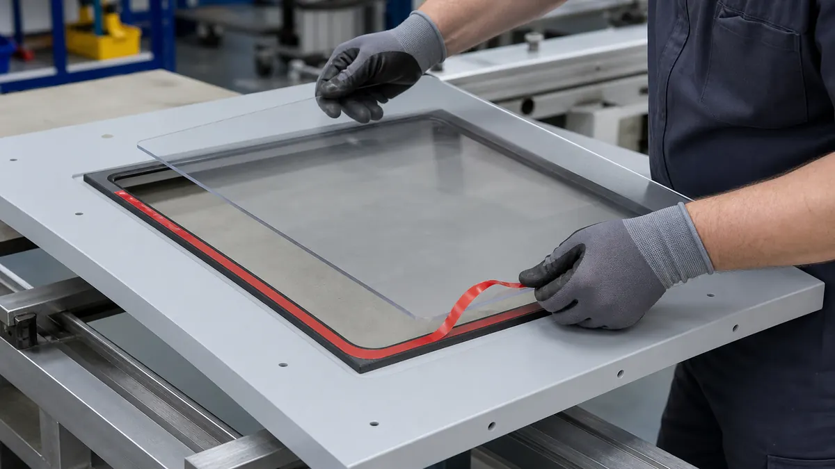
Document every point where the material changes direction or support. Include unwind shaft, core, flanges, guides, tension control, sensors, drive rollers, peel plate, vacuum head, camera, receiving fixture and waste take-up. Note whether the cell peels the liner away from a stationary part, lifts the part from a flat web or uses another approved presentation method.
The receiving surface matters too. The adhesive may be placed on metal, glass, painted plastic, foam, fabric, a gasket or another converted layer. Define whether the tape is a temporary positioning aid or remains in the final assembly. The release liner only controls delivery; it does not qualify the permanent bond, gasket compression, environmental durability or product function.
| Cell input | What to document | Why it matters |
|---|---|---|
| Unwind | Core, maximum roll diameter, winding side, brake and flange clearance | Prevents reversed loading and unstable tension |
| Web path | Guides, bend radii, rollers, peel angle and supported spans | Controls curl, tracking and premature release |
| Detection | Vision or sensor type, contrast, fiducials and inspection zone | Supports part registration and missing-part detection |
| Pickup | Vacuum cup, needle, gripper, contact zone and approach | Defines required part presentation and surface access |
| Placement | Datum, pressure path, substrate condition and cycle sequence | Separates delivery controls from final bond qualification |
Select the Release Liner System
Liner material and stiffness
Paper and film liners offer different stiffness, moisture response, tear behavior, dimensional stability, sensor interaction and waste handling. A stiffer liner may track well across an unsupported span but resist a tight peel plate. A thin film may bend readily yet require different tension and static controls. Select using the real web path.
Release coating and release balance
The release coating must protect the adhesive through conversion, winding, storage and feed, then let the part separate at the intended point. For a double-liner construction, define which liner removes first and whether the two sides need different release levels. Excessively easy release can cause parts to shift or lift in the roll; difficult release can deform the part or overload the pickup step.
Flatness, cleanliness and static
Track curl direction, moisture conditioning, coating uniformity, dust, silicone transfer limits, edge debris and electrostatic behavior where relevant. Cleanroom, optics, electronics or painted-surface assemblies may need tighter packaging and handling controls than general fabrication. State these requirements in the RFQ rather than assuming a generic liner grade.
| Liner choice | Potential fit | Question to validate |
|---|---|---|
| Supercalendered paper | Stable general converting and hand/automatic feeds | How does moisture and bend radius affect flatness? |
| Film liner | Dimensional control, transparency or tight web paths | Can the cell manage static, tracking and waste take-up? |
| Poly-coated paper | Balanced stiffness and surface uniformity | Does the laminate remain flat through storage and feed? |
| Two-sided differential release | Double-liner or staged exposure sequences | Which side releases first under real peel conditions? |
| Custom printed or marked liner | Orientation and vision-assisted placement | Are marks stable, readable and outside functional surfaces? |
Design Part Pitch, Matrix and Splices
Define part orientation, pitch, cross-web position, minimum edge margin, indexing feature, leader and trailer lengths, matrix-removal state and roll quantity. Leave the pickup head a clear contact zone and make sure the peel action exposes the part without flipping a corner. If the part has a pull tab, split liner or adhesive-free zone, locate it from the same datum used by the cell.
Specify whether splices are prohibited, allowed only in the leader/trailer or permitted with a machine-readable flag and automatic reject. A hidden splice can change thickness, tension and sensor response. Packaging labels should identify part revision, roll direction and loading orientation without placing contamination against the liner edge.
Recommended Buying and Qualification Workflow
- Define the adhesive role. Confirm substrates, permanent or temporary function, bondline and final tests.
- Map the equipment. Record the complete unwind-to-placement path and operating limits.
- Release the converted drawing. Include part geometry, pitch, datums, tabs, matrix and tolerances.
- Specify the liner system. State material, thickness, release sequence, coating side and cleanliness needs.
- Define roll presentation. Set core, OD, winding, leader, trailer, splice and packaging rules.
- Build engineering rolls. Convert representative material across the intended web width.
- Run the full cell. Include startup, steady production, stop/restart and roll change.
- Inspect both part and waste. Check release, adhesive transfer, curl, liner tears and missing parts.
- Verify final placement. Measure position, pressure, bond and downstream assembly acceptance.
- Freeze the purchase specification. Record approved materials, converting controls and change notification.
Validate Feed, Pickup and Final Bond
Engineering trials should include the intended adhesive lot, liner lot, roll positions, die-cut tool, machine setup and representative storage/conditioning. Test normal speed, low and high approved tension, starts, stops, partial rolls and the maximum allowed dwell at the peel point. The aim is not only to complete one successful cycle but to show stable presentation across the planned production window.
| Validation group | What to observe | Release question |
|---|---|---|
| Web handling | Tracking, telescoping, curl, wrinkles, tension and edge damage | Does the liner reach the peel point consistently? |
| Part release | Corner lift, premature release, adhesive roll-up and matrix interaction | Does every part present in the intended orientation? |
| Detection/pickup | Sensor signal, vision registration, double pickup and vacuum stability | Can the cell identify and lift one part reliably? |
| Placement | Datum accuracy, stretch, rotation, pressure and liner removal | Is the part positioned without distortion? |
| Final assembly | Bond, fit, compression, appearance and product-level tests | Does the complete released assembly perform as required? |
Troubleshoot Liner and Presentation Defects
Premature part lift may come from release level, roll compression, curl, small bend radii, excessive tension or incomplete matrix removal. Failure to pick can involve difficult release, an unsuitable vacuum contact area, distorted parts, liner bounce or pickup timing. Web wandering can involve core fit, winding quality, edge damage, uneven tension or guide setup.
Do not solve every issue by changing release coating. Preserve the failed roll position and compare part geometry, die strike, liner caliper, adhesive ooze, winding, storage, static and cell settings. A converting defect and a feeder defect can produce the same symptom, so change one controlled variable and review the empty liner as carefully as the placed part.
Related Products and Articles
Frequently Asked Questions
Is a paper or film release liner better for automation?
Neither is universally better. Choose from the real bend radius, tension, stiffness, moisture, static, sensor, cleanliness and waste-handling requirements of the cell.
What is differential release?
It is a designed difference in release behavior between liner faces or between two liners, used to control which liner separates first in a staged assembly sequence.
Can the liner color be used for machine detection?
Only after testing with the actual sensor or vision system, lighting, adhesive part and contamination state. Color names alone do not define optical response.
Should splices be allowed in production rolls?
The equipment and quality owners must decide. If allowed, specify location, construction, identification, automatic reject logic and traceability; otherwise prohibit them explicitly.
What information belongs in an automated-placement RFQ?
Provide adhesive role, substrates, part drawing, liner path, peel method, pickup tool, sensors, roll direction, core and OD, pitch, matrix, splice rule, speed range, environment and final tests.
Specify a Machine-Ready Adhesive Roll
Share the converted-part drawing, adhesive function, substrate stack, feeder and peel-path details, pickup method, vision or sensor requirements, roll envelope, winding orientation, cleanliness class, annual volume and validation plan. JIAO TAO TAO can prepare double-sided tape parts and liner formats for controlled automation trials.
Discuss double-sided tape liner design
Industrial Double-Sided Tape for Appliance Decorative Panel Bonding
Related Article

Need help choosing the right industrial tape?
Send us your application details, including temperature, surface material, size, quantity and current problem. Our team will help recommend a suitable tape material or custom die-cut solution.

simon@jiaotaotao.com


+86-136 1277 5969


+86-136 1277 5969
