
PTFE Tape for PVC Window Profile Welding Machines
PTFE Tape for PVC Window Profile Welding Machines
PTFE tape for PVC window welding machines creates a replaceable release surface where heated tooling contacts softened uPVC profile material. A suitable tape can help control sticking and simplify tooling maintenance, but it must match the welding head, pressure, temperature, profile geometry, and cleaning method. It cannot correct an incorrect welding recipe or worn machine alignment.

Key Takeaways
- PTFE-coated fiberglass tape is used as a non-stick release layer on selected plastic-welding surfaces.
- The tape’s weave, thickness, adhesive, edge layout, and installation quality can affect the weld interface.
- Machine temperature, pressure, dwell, profile material, and tooling alignment remain part of weld validation.
- Replace the tape before damage, wrinkles, or contamination reaches the active welding zone.
What PTFE Tape Does on a PVC Profile Welding Machine
In PVC window fabrication, heated tooling softens the prepared profile ends before the corners are brought together under controlled pressure. Selected machine designs use a PTFE-faced layer on the hot plate or adjacent contact surface so softened polymer is less likely to adhere directly to the metal. The tape becomes a service component that can be inspected and replaced.
The release layer does not set the weld temperature, melt depth, pressure, allowance, cooling time, or corner-cleaning result. A weak, distorted, or inconsistent corner can come from profile formulation, reinforcement, cut accuracy, heater calibration, plate parallelism, contamination, weather, or process settings. Treat PTFE tape as one controlled element in the approved welding process.
PTFE Film Tape vs PTFE-Coated Fiberglass Tape
| Construction | Potential benefit | What to verify on the welder |
|---|---|---|
| PTFE-coated fiberglass adhesive tape | Reinforced structure for repeated contact and handling | Surface texture, thickness, edge durability, and adhesive stability |
| Skived PTFE film adhesive tape | Smoother, thinner release face | Tear resistance, puncture risk, wrinkling, and machine-maker approval |
| Liner-backed converted PTFE part | Controlled shape and protected adhesive before placement | Registration, liner release, corner radii, and replacement method |
| Mechanically retained PTFE cover | Avoids adhesive on selected tooling designs | Only where the equipment is designed for the retained cover |
Machine and Process Data for Tape Selection
| Parameter | Data to provide | Why it matters |
|---|---|---|
| Welder configuration | Machine model, single-head or multi-head layout, and plate drawing | Defines usable tape geometry and installation access |
| Tooling dimensions | Active surface length, width, radii, and clearance in mm | Controls the converted shape and edge position |
| Thermal cycle | Measured plate temperature in °C and heating dwell in seconds | Must remain within the approved tape construction window |
| Welding load | Pressure or force setting, clamping sequence, and cycles per shift | Influences wear, compression, and edge movement |
| Profile system | uPVC formulation, surface finish, color, geometry, and reinforcement | Changes heat transfer, melt behavior, and contact pattern |
| Cleaning process | Approved cleaner, tool, interval, and plate condition | Affects adhesive contact and service life |
| Acceptance criteria | Corner appearance, weld strength method, residue, and dimensional checks | Connects the tape trial to the finished window requirement |
How to Design the PTFE Tape Layout
Keep seams away from the critical contact zone
Where multiple strips are unavoidable, define the joint direction and position so a tape step does not print into the softened profile or collect melted polymer. A converted one-piece shape may improve repeatability when the plate geometry and replacement volume justify it.
Protect edges from scraping and peel forces
Sharp tooling corners, burrs, aggressive cleaning, and profile movement can attack a tape edge. Round the converted tape corners where the machine permits, remove exposed adhesive, and avoid placing an unsupported edge in the direction of repeated material travel.
Do not stack new tape over worn tape
Layering over a damaged release surface changes thickness and may trap contamination or degraded adhesive. Unless the equipment procedure explicitly permits an overlay, remove the old layer, inspect the metal, and install the approved construction on a prepared surface.
PTFE Tape Installation Procedure
- Lock out, cool, and secure the machine. Follow the equipment owner’s safety procedure and verify a safe maintenance temperature.
- Remove the worn release layer carefully. Use the approved method so the plate finish and flatness are not damaged.
- Inspect the tooling. Check for burrs, dents, polymer deposits, corrosion, scratches, and old adhesive.
- Clean with a compatible agent. The surface should be dry and free of lint, oil, cleaner residue, and loose particles.
- Dry-fit the converted piece. Confirm orientation, edge clearance, openings, and seam position before exposing adhesive.
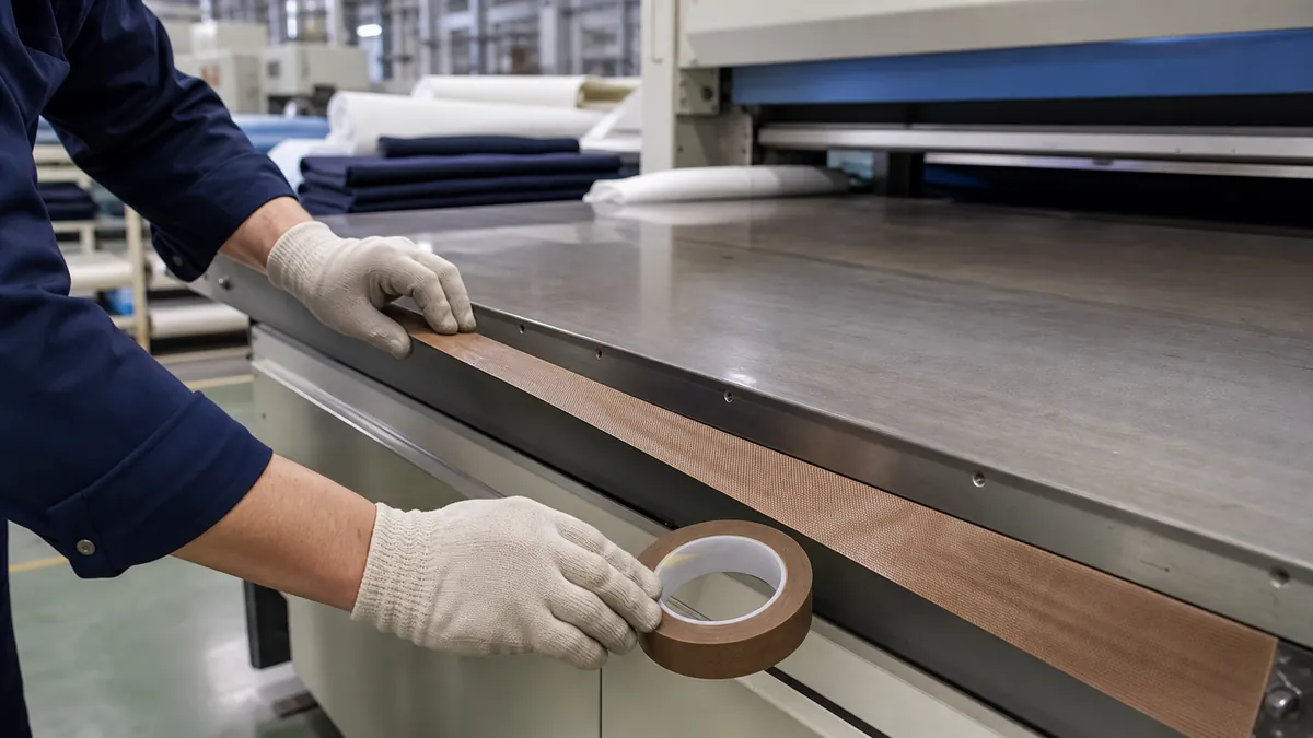
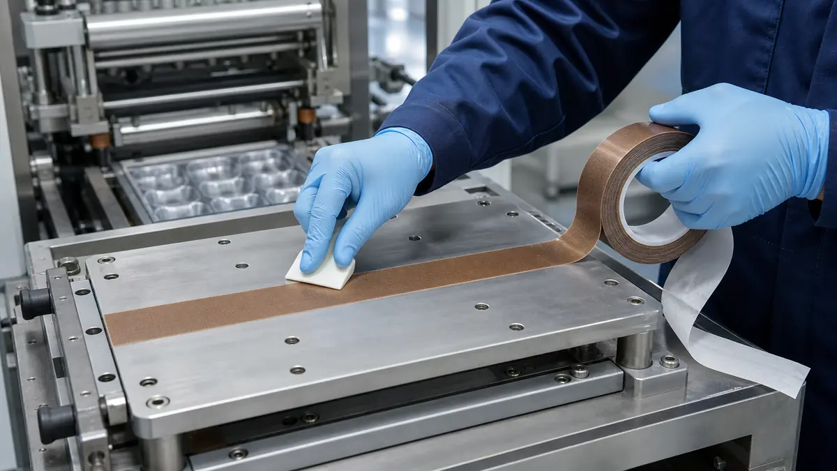
- Apply without stretching. Roll the tape progressively from one edge and push air toward the free side.
- Inspect the active face. Reject wrinkles, bubbles, pinholes, lifted edges, folds, and exposed adhesive.
- Requalify the weld. Return to the approved machine setup and inspect initial corners before routine production.
Maintenance and Replacement Triggers
- The PTFE face is cut, abraded, glazed, punctured, or contaminated.
- A bubble, wrinkle, overlap, or lifted edge reaches the profile contact area.
- Molten material begins sticking after temperature and profile causes are checked.
- Adhesive migrates beyond an edge or transfers during removal.
- The tape shifts, shrinks, or exposes the underlying plate.
- The defined preventive-maintenance interval or cycle count is reached.
Troubleshooting PVC Window Welder Release Surfaces
| Problem | Tape-related checks | Other machine checks |
|---|---|---|
| Profile sticks to the hot plate | Worn PTFE face, contamination, exposed seam, puncture | Plate temperature, dwell, profile formulation, and heater calibration |
| Corner shows a surface mark | Tape texture, overlap, wrinkle, trapped debris | Plate flatness, pressure, alignment, and profile cut |
| Tape lifts at one edge | Cleaning, application pressure, cut quality, adhesive compatibility | Scraping contact, plate damage, profile travel, and maintenance handling |
| Adhesive remains on the plate | Exposure window, adhesive grade, removal condition | Cleaning chemistry and previous maintenance history |
| Weld result varies by head | Tape thickness, placement, wear, and trapped air on each head | Head calibration, heater output, pressure, and timing balance |
Related Products and Articles
- Explore PTFE film and PTFE-coated fiberglass tape constructions.
- Review how to apply PTFE tape on industrial machine surfaces.
- Compare backing options in the PTFE-coated fiberglass cloth selection guide.
- Send the welding plate drawing and maintenance conditions for a tape review.
Technical References
- Saint-Gobain CHR SGC5-6 product information identifies PTFE-coated fiberglass tape as a release surface for PVC window welding.
- Saint-Gobain CHR SG16 product information describes PTFE-coated fiberglass tape for repeated industrial release and guide surfaces.
Frequently Asked Questions
Which PTFE tape is used on PVC window welding machines?
PTFE-coated fiberglass adhesive tape is commonly considered where a reinforced, non-stick release surface is required. The exact grade, thickness, adhesive, and converted shape must be approved for the machine and profile system.
Can PTFE tape improve a weak PVC corner weld?
It may restore a controlled release surface when the existing layer is damaged, but it does not replace correct temperature, dwell, pressure, profile preparation, alignment, or cooling. Diagnose the welding process as a complete system.
Should PTFE tape overlap on the heater plate?
Only if the machine procedure allows it. An overlap creates a thickness step that may mark the profile. A butt joint can open or collect debris, so joint position and direction require validation.
How often should the PTFE tape be replaced?
Use a condition-based limit and a preventive interval derived from the real cycle count, cleaning method, profile contact, and weld acceptance results. Replace it before damage reaches the active zone.
Can old adhesive be scraped off with a metal blade?
Follow the machine maker’s maintenance method. Aggressive scraping can change plate flatness or finish. Use only tools and cleaners approved for the tooling material.
Specify a PTFE Release Tape for Your PVC Welder
Provide the welding machine model, plate drawing, measured thermal cycle, profile construction, pressure or force setting, cleaning method, current wear pattern, and required tape presentation. JIAO TAO TAO can help compare PTFE film and reinforced PTFE tape for your own machine validation.
Custom Die-Cut Tape for LCD Backlight Light-Leak Control
Related Article
Need help choosing the right industrial tape?
Send us your application details, including temperature, surface material, size, quantity and current problem. Our team will help recommend a suitable tape material or custom die-cut solution.

simon@jiaotaotao.com


+86-136 1277 5969


+86-136 1277 5969
