
PTFE Tape for Blister Packaging Heat-Seal Plates
PTFE Tape for Blister Packaging Heat-Seal Plates
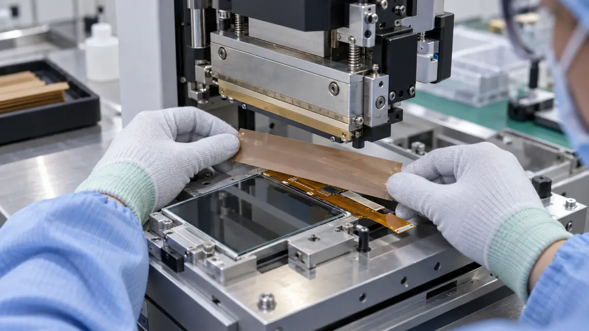
PTFE tape for blister packaging heat-seal plates creates a replaceable, non-stick interface where heated tooling repeatedly contacts lidding material and formed pockets. Adhesive-backed PTFE film or PTFE-coated fiberglass constructions can help reduce sticking and simplify maintenance, but only when the tape matches the plate geometry, thermal cycle, contact pressure and required surface finish. This guide covers specification, installation and inspection without replacing the packaging machine maker’s setup or validated sealing process.
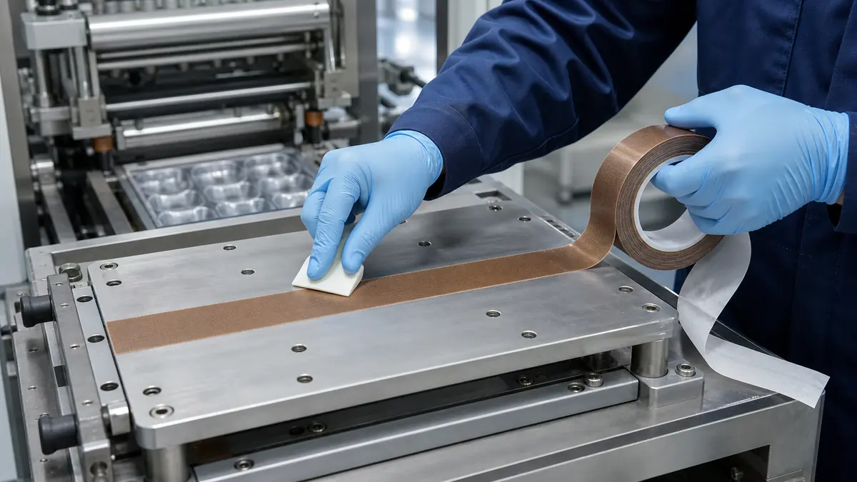
What the PTFE Layer Does on Heat-Seal Tooling
A blister packaging station controls heat, pressure and dwell to form a seal between the package components. A PTFE-faced layer may be used on selected contact surfaces to reduce adhesion of softened polymer, coating or stray seal material. It can also act as a service part that is replaced before the underlying tooling is damaged or heavily contaminated.
The tape does not correct an incorrect sealing window. Weak seals, channel leaks, distorted blisters or print damage can come from temperature, pressure, alignment, material variation or tooling condition. Treat PTFE tape as one controlled part of the maintenance and validation system.
PTFE Film and PTFE-Coated Fiberglass Compared
| Construction | Selection Advantage | Check Before Use |
|---|---|---|
| Skived PTFE film tape | Smooth, thin release surface for controlled contact areas | Conformability, puncture risk and adhesive support at operating heat |
| PTFE-coated fiberglass tape | Reinforced structure for repeated mechanical contact | Fabric texture, edge thickness and imprint risk on the package |
| Zone tape or custom-cut shape | Adhesive is limited to designed areas or geometry | Tooling fit, orientation, replacement method and availability |
| Mechanically retained PTFE cover | Can avoid adhesive in selected machine designs | Requires compatible tooling and machine-maker approval |
Heat-Seal Plate Information for the RFQ
| Parameter | Information to Provide | Effect on Selection |
|---|---|---|
| Machine and station | Machine model, plate drawing and tape location | Defines usable dimensions and installation access |
| Thermal profile | Set point, measured surface range, dwell and cycles per shift | Influences backing, adhesive and replacement interval |
| Contact load | Pressure, actuation method and plate flatness | Affects wear, cold flow and visible marking |
| Packaging materials | Formed web, lidding structure, coatings and inks | Helps assess release behavior and contamination risk |
| Plate surface | Metal, coating, finish and cleaning chemistry | Controls adhesive wet-out and removal |
| Acceptance criteria | Seal integrity, appearance, print quality and residue limits | Connects tape choice to the validated package outcome |
Installation Procedure
1. Lock out, cool and inspect the station
Follow the equipment owner’s safety procedure and confirm that the plate is at a safe maintenance temperature. Remove worn tape using the approved method. Inspect the metal for burrs, dents, old adhesive, deposits and flatness changes before installing a new layer.
2. Clean the plate with an approved agent
Use a cleaning method compatible with the tooling and machine. The surface should be dry and free from lint, release agent and softened adhesive. Avoid scraping that changes the plate finish or geometry.
3. Cut the tape without damaging the release face
Use a template, cutting fixture or converted part when geometry is repeated. Keep cut edges smooth and avoid pinholes, creases and contamination on the adhesive. For several adjoining pieces, define the overlap or butt-joint direction relative to web travel.
4. Apply from one edge with uniform pressure
Lay the tape without stretching. Use a suitable roller or squeegee to move air toward the free edge. Do not trap bubbles in the active sealing zone. Trim only where the maintenance instruction permits, and keep blades away from the plate surface.
5. Requalify the station after replacement
Bring the station back to its validated operating condition and inspect initial packs. Confirm seal appearance, adhesion, registration and any required package-integrity test before routine production resumes.
Maintenance and Replacement Triggers
- Wrinkles, bubbles or lifted edges enter the active seal area.
- The release face is cut, abraded, glazed or contaminated.
- Seal appearance or package registration changes after other causes are ruled out.
- Adhesive creeps beyond the tape edge or transfers during removal.
- The tape seam begins to print through or collect debris.
- The preventive-maintenance interval defined by the validated process is reached.
Troubleshooting Table
| Observed Issue | Tape-Related Checks | Other Process Checks |
|---|---|---|
| Material sticks to the plate | Surface contamination, worn PTFE face, puncture or exposed seam | Temperature, dwell, coating and web material |
| Visible seal marks | Tape texture, wrinkles, overlap and trapped debris | Plate pressure, flatness and tooling alignment |
| Tape lifts at an edge | Cleaning, application pressure, thermal expansion and cut quality | Plate damage, web contact and maintenance handling |
| Adhesive residue on tooling | Adhesive grade, exposure time and removal temperature | Cleaning chemical and removal technique |
| Seal strength varies | Tape thickness variation, local damage and air pockets | Heat, pressure, dwell, web tension and material lot |
FAQ
Which PTFE tape is best for a blister packaging heat-seal plate?
The best construction depends on the plate finish, surface smoothness, contact pressure, thermal cycle and wear pattern. Compare PTFE film and reinforced PTFE-coated fiberglass on the actual station.
Can PTFE tape improve a weak blister seal?
It may provide a controlled release surface, but it does not replace correct heat, pressure, dwell, alignment or packaging materials. Diagnose the sealing window first.
Should PTFE tape overlap on the heat-seal plate?
Only when the machine and package design allow it. An overlap can create a thickness step, while a butt joint can open or collect debris. Validate the joint location and direction.
How often should the tape be replaced?
Use condition-based checks and a preventive interval derived from the real cycle rate, tooling contact, cleaning method and package acceptance results.
Related Products and Articles
- High-temperature PTFE tape product range
- How to use PTFE tape on industrial machine surfaces
- PTFE-coated fiberglass cloth selection guide
Request a Tooling Trial
To evaluate PTFE tape for blister packaging heat-seal plates, send JIAO TAO TAO the machine and plate details, measured temperature range, pressure, dwell, package materials, cleaning method and current failure mode. The technical team can help shortlist constructions for a controlled maintenance trial. Send your heat-seal application details.
Acetate Cloth Tape for Transformer Lead Exit Reinforcement
Custom Die-Cut Tape for LED Lighting Assembly
Related Article
Need help choosing the right industrial tape?
Send us your application details, including temperature, surface material, size, quantity and current problem. Our team will help recommend a suitable tape material or custom die-cut solution.

simon@jiaotaotao.com


+86-136 1277 5969


+86-136 1277 5969
