
Industrial Double-Sided Tape for Touchscreen Bezel Bonding
Industrial Double-Sided Tape for Touchscreen Bezel Bonding
Industrial double-sided tape for touchscreen bezel bonding creates a thin, clean attachment between cover glass, touch sensors, display frames, and equipment housings. The adhesive frame must hold position, manage the real surface finishes, stay outside the active optical area, and support the enclosure’s environmental and service requirements. Selection starts with the full display stack and assembly process, not peel strength alone.

Key Takeaways
- Map every bonded surface: glass treatment, ink border, metal coating, plastic grade, texture, and contamination control.
- Balance adhesive wet-out, carrier thickness, gap filling, optical keep-out, seal continuity, and rework.
- Use die-cut geometry, liner tabs, and placement datums to control the adhesive frame during assembly.
- Validate the finished touchscreen enclosure for bond durability, appearance, function, environment, and service procedure.
What the Touchscreen Bezel Bondline Must Do
Industrial touchscreens appear in machine controls, kiosks, medical and laboratory equipment, transport displays, appliance interfaces, and outdoor terminals. The visible module may combine cover glass, decorative ink, a touch sensor, an LCD or OLED assembly, a plastic or metal bezel, a gasket, and a rear housing. A double-sided adhesive frame can retain one layer, seal a perimeter, prevent movement, and simplify fastener-free assembly.
Those functions are related but not identical. A tape that holds a prototype at room temperature may still allow edge lift, light leakage, contamination ingress, glass stress, or display movement after temperature cycling, vibration, cleaning, or enclosure opening. Define the primary function and measurable acceptance criteria before comparing tape families.
Common Double-Sided Tape Constructions Compared
| Construction | When it may fit | Key limitation to check |
|---|---|---|
| Transfer adhesive | Very thin bondline and conformable adhesive coverage are required | No carrier for handling; gap filling and die-cut stability may be limited |
| Double-coated PET tape | Thin, dimensionally stable converted frames and controlled handling are needed | Limited ability to bridge deep texture or large tolerance variation |
| Double-coated foam tape | Gap filling, stress distribution, cushioning, or surface texture requires compliance | Added thickness, compression set, edge visibility, and optical spacing |
| Black double-sided tape | The bondline needs opacity or a dark appearance behind a printed border | Color does not guarantee light blocking, adhesion, or environmental durability |
| Removable or reworkable adhesive | The service plan requires controlled module replacement | Retention margin and removal method must still meet the use environment |
Touchscreen Bonding Data Required for an RFQ
| Design input | Record it as | Why it matters |
|---|---|---|
| First surface | Glass, ceramic ink, anti-glare or anti-fingerprint treatment, coating, and roughness | Controls adhesive contact and possible coating failure |
| Second surface | Aluminum, stainless steel, coated metal, ABS, PC, blend, or other identified polymer | Defines surface energy, texture, stiffness, and environmental response |
| Bond geometry | Outer and inner dimensions, minimum land width, corner radius, holes, notches, and tolerance | Sets available adhesive area and die-cut feasibility |
| Stack and gap | Nominal and worst-case height, flatness, bow, and compression in mm | Determines whether a thin film or conformable foam carrier is appropriate |
| Optical boundary | Active area, view opening, black border, light-leak limit, and adhesive offset | Prevents adhesive or liner features from entering the visible area |
| Environment | Temperature, humidity, UV, cleaning fluids, vibration, impact, and service duration | Defines the durability sequence for the complete assembly |
| Assembly format | Manual or automated placement, sheet or roll, liner split, tab, and fixture datum | Controls handling, takt time, and placement repeatability |
How to Choose Adhesive, Carrier, and Liner
Test both surfaces, including coatings and ink
The adhesive may bond to a decorative ink layer rather than bare glass, and to paint or a molded texture rather than bulk metal or plastic. The weakest interface can be the ink-to-glass or coating-to-housing bond. Use production-representative surface lots and record the failure mode after the planned dwell and environmental exposures.
Select thickness from the worst-case gap
A thin PET carrier supports precise die cutting and a low profile when the surfaces are flat and parallel. Foam can accommodate texture and tolerance while distributing stress, but it changes the stack height and may be visible at the edge. Compare the entire enclosure tolerance, not only the drawing’s nominal gap.
Control opacity and edge appearance separately
A black carrier or adhesive can help hide the bondline behind a decorative border, but an opaque appearance does not automatically prevent light leakage through joints, cut edges, thin sections, or liner-tab features. Inspect the assembled display under the intended backlight level and viewing angles.
Design the liner for placement
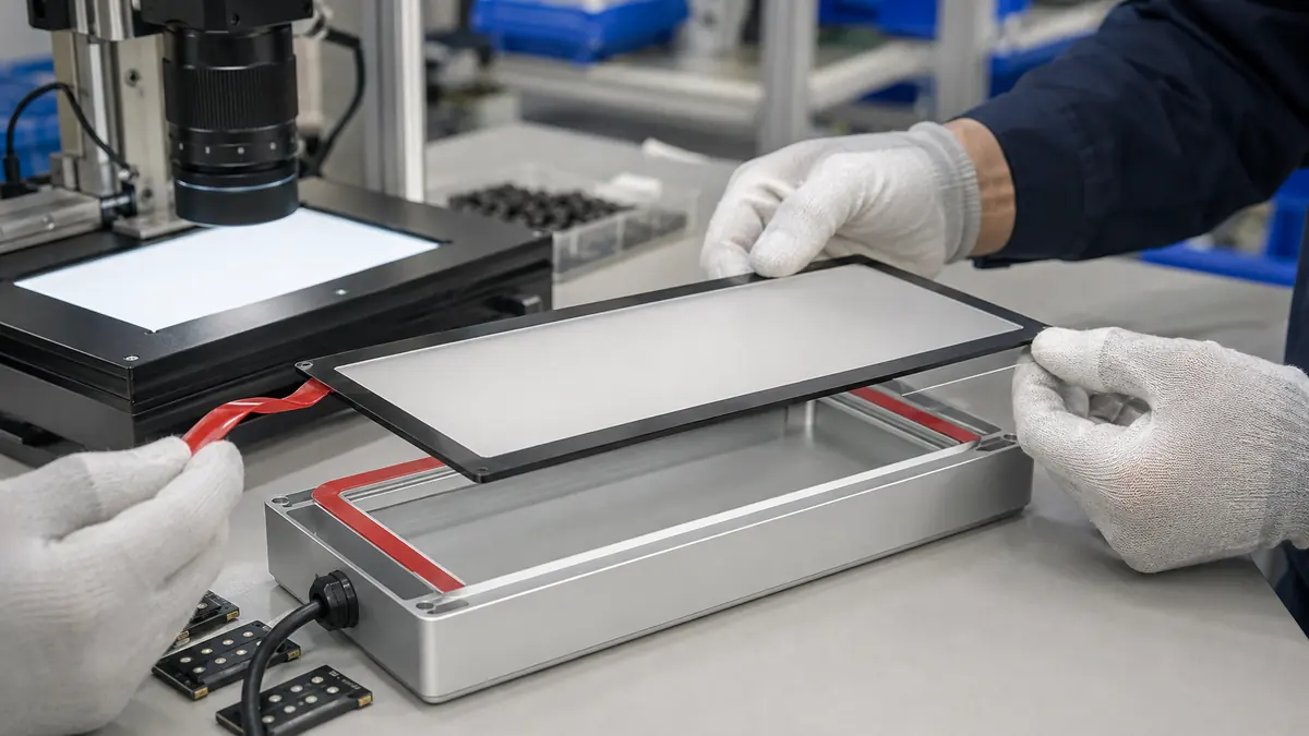
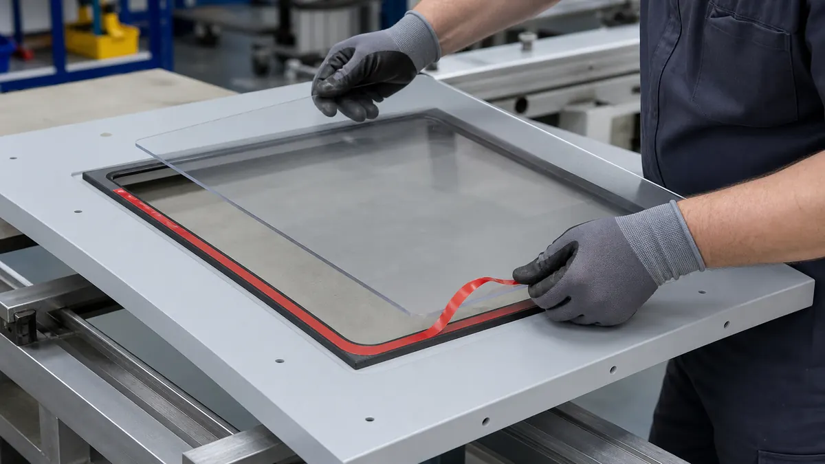
Split liners, extended pull tabs, rigid polyester carriers, and kiss-cut presentation can let an operator expose only part of the adhesive, align to fixture pins, tack the frame, and then remove the remaining liner. The release balance must allow clean removal without lifting or stretching narrow adhesive lands.
Plan rework before finalizing adhesion
Some modules are permanent, while others must be replaced without breaking cover glass, damaging the sensor, or scraping the housing. Define heat, solvent, pull-tab, cutting-wire, or mechanical separation limits within the service procedure. Reworkability should be tested after aging, not only immediately after assembly.
Recommended Die-Cutting and Assembly Workflow
- Release a controlled adhesive drawing. Define outer and inner profiles, offsets, joints, holes, corner radii, liner splits, pull tabs, and datums.
- Condition and identify the materials. Keep glass, printed borders, sensors, bezels, adhesive, and liners within the approved storage and handling process.
- Clean with an approved method. Remove particles, fingerprints, mold release, machining fluid, and packaging residue without damaging optical coatings or ink.
- Load the part into a stable fixture. Support the glass and prevent the module from rocking, bowing, or contacting a hard particle.
- Expose the first liner zone. Avoid touching adhesive, stretching narrow rails, or removing the entire liner before alignment when the process uses staged placement.
- Align and laminate from a datum. Press progressively with controlled force so air is not trapped and the adhesive stays outside the view opening.
- Apply the specified pressure and dwell. Use a roller, platen, or fixture that supports the complete bond area without stressing the display.
- Inspect the finished module. Check placement, liner removal, wrinkles, edge lift, squeeze-out, contamination, light leakage, touch function, and enclosure fit.
Validation and Troubleshooting
| Observed issue | Adhesive-part checks | Assembly checks |
|---|---|---|
| Corner lift | Corner radius, minimum land width, adhesive wet-out, carrier stiffness | Surface cleaning, part bow, pressure, dwell, cable or housing stress |
| Light leakage | Frame continuity, opacity, joint, offset, cut quality, thin rail | Backlight level, bezel gap, alignment, viewing angle, enclosure closure |
| Adhesive visible in active area | Inner-profile tolerance, liner stretch, adhesive flow, part shrinkage | Fixture datum, camera alignment, placement sequence, operator access |
| Glass or display stress | Tape thickness, foam compression, local overlap, stiffness transition | Flatness, clamp force, fastener pattern, housing tolerance, trapped debris |
| Module shifts in service | Shear resistance, adhesive coverage, carrier creep, environmental compatibility | Temperature, vibration, impact, cable load, insufficient dwell |
| Rework damages the module | Adhesive strength after aging, pull-tab design, foam split behavior | Removal temperature, angle, speed, cutting tool, service access |
Approve the complete display assembly using defined visual, dimensional, functional, mechanical, and environmental tests. Useful evidence includes the substrate and coating lots, tape lot, converted-part drawing revision, liner orientation, fixture revision, application pressure, dwell, placement data, environmental sequence, and failure mode. Do not turn a supplier’s typical tape value into a finished-display guarantee.
Related Products and Articles
- Compare industrial double-sided tape constructions for thin film, transfer, foam, and converted bonding formats.
- Review custom die-cutting options for perimeter frames, liner tabs, holes, and placement carriers.
- See the custom die-cut tape guide for precision assembly.
- Send your display stack and adhesive-frame drawing for material-format review.
Frequently Asked Questions
What double-sided tape is used for touchscreen bezels?
Thin transfer adhesive, double-coated PET tape, and double-coated foam tape are common routes. The right construction depends on the two real surfaces, flatness, gap, optical boundary, environment, thickness budget, and rework plan.
Is foam tape better than thin PET double-sided tape?
Neither is universally better. Foam can bridge texture and tolerance, while PET provides a thinner and more dimensionally stable carrier. Compare the worst-case stack, stress, edge appearance, optical opening, and service environment.
How narrow can a die-cut adhesive bezel be?
The practical land width depends on material construction, converting tolerance, corner geometry, liner support, placement accuracy, available bond area, and required retention. Confirm it through converted-part trials rather than a generic minimum.
Can black double-sided tape stop touchscreen light leakage?
It can contribute to an opaque perimeter, but the complete frame continuity, joint, cut edges, adhesive offset, bezel gap, and backlight condition determine the result. Validate the assembled display under intended viewing conditions.
Can touchscreen adhesive frames be supplied on a carrier liner?
Yes. Kiss-cut frames on a stable liner can include split liners, pull tabs, locating holes, and orientation features for manual or automated placement. Release balance and carrier stiffness should match the assembly method.
Develop a Touchscreen Bezel Adhesive Frame
Share the glass and ink system, bezel material and finish, bond dimensions, worst-case gap, optical keep-out, environmental requirements, rework method, drawing, annual volume, and preferred liner presentation. JIAO TAO TAO can help compare double-sided film, transfer, and foam tape formats for your own validation.
Industrial Double-Sided Tape for Control Cabinet Gasket Positioning
Industrial Double-Sided Tape for EMI Gasket Lamination
Related Article
Need help choosing the right industrial tape?
Send us your application details, including temperature, surface material, size, quantity and current problem. Our team will help recommend a suitable tape material or custom die-cut solution.

simon@jiaotaotao.com


+86-136 1277 5969


+86-136 1277 5969
