
Industrial Double-Sided Tape for Machine-Vision Light Diffuser Bonding
Buying Guides · Machine-Vision Lighting
Industrial Double-Sided Tape for Machine-Vision Light Diffuser Bonding
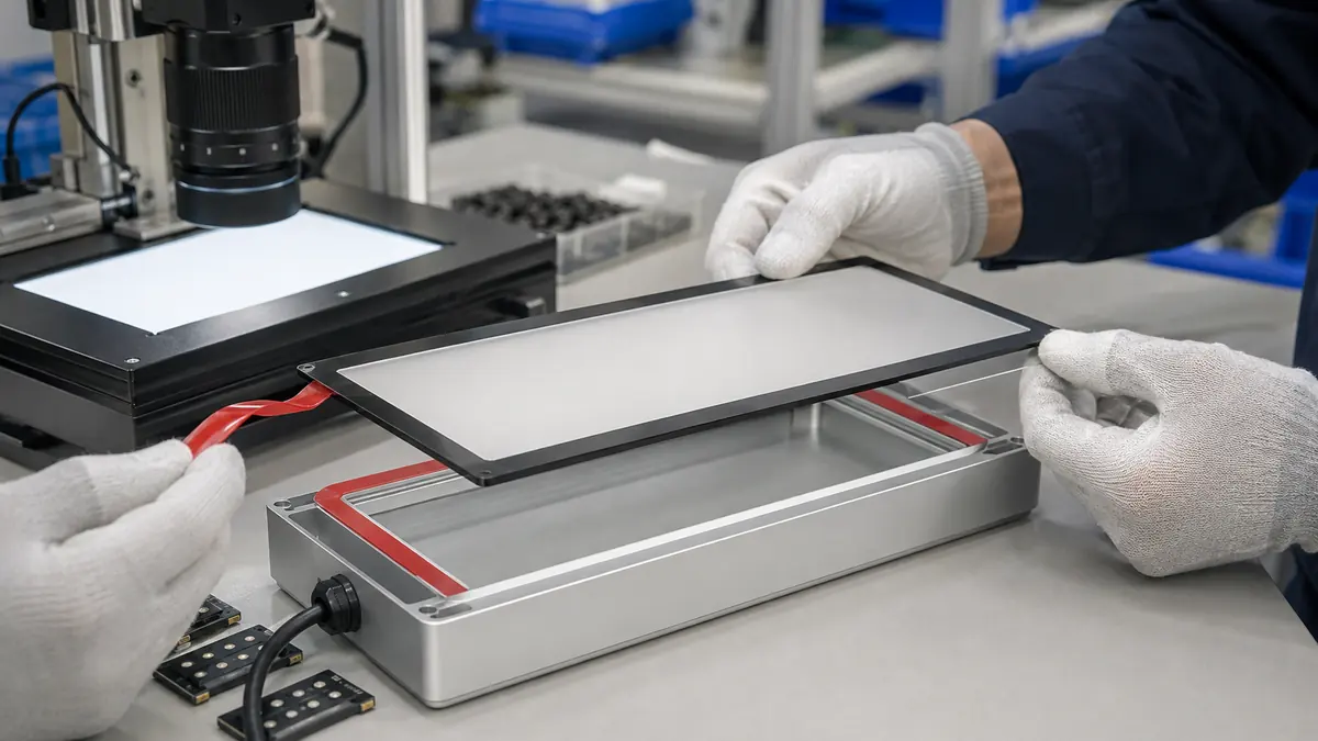
Industrial double-sided tape for machine-vision light diffuser bonding can join a frosted optical panel to a metal or polymer lighting housing while controlling bondline thickness and assembly cleanliness. The choice must account for optical keep-outs, diffuser stress, housing finish, heat, cleaning, tolerances, and any required mechanical retention.
Quick Answer
Choose double-sided tape for a machine-vision diffuser only after defining both substrates, the adhesive footprint, optical aperture, heat path, cleaning environment, expected life, and service method. Thin PET-carrier tape can suit smooth, closely matched surfaces and a low-profile bond. Foam tape can accommodate texture or small gaps, but its thickness, compression, edge visibility, and long-term creep require separate validation.
Define the Light Assembly Before Selecting Tape
Machine-vision lights may use rectangular, bar, ring, dome, coaxial, or custom housings. A diffuser can distribute illumination, protect LEDs, close an opening, or serve as one layer in an optical stack. Each function changes the permitted bond area and the consequence of movement. Record whether the panel is acrylic, polycarbonate, glass, or another qualified optical material and whether the housing is anodized aluminum, painted metal, molded polymer, or a coated component.
Map the load path. The tape may carry only the light diffuser’s mass, or it may also see cable handling, vibration, thermal expansion, orientation changes, cleaning pressure, and shock during machine service. If loss of the diffuser creates a safety or contamination risk, the product owner should evaluate mechanical retention in addition to adhesive bonding.
| Design input | Questions to answer | Why it matters |
|---|---|---|
| Diffuser | Material, thickness, surface finish, coatings, and edge quality | Controls wet-out, stress sensitivity, and optical appearance |
| Housing | Material, finish, texture, flatness, joints, and heat source | Controls real contact area and thermal movement |
| Optical aperture | Active area, LED spacing, keep-out, and permitted shadow | Defines the inside edge of the tape frame |
| Environment | Temperature, vibration, cleaner, oil mist, dust, and humidity | Changes adhesion and aging requirements |
| Service strategy | Permanent assembly, replaceable diffuser, or field repair | Changes adhesion target and disassembly method |
Compare Industrial Double-Sided Tape Options
Thin PET-carrier tape
A PET carrier can support precise converting, stable frame geometry, and a low-profile bond between smooth surfaces. It offers little gap accommodation, so flatness, housing joints, coating texture, and diffuser bow must remain within the qualified range. Transparent adhesive does not make an in-aperture bond optically invisible.
PE, EVA, or acrylic foam tape
Foam can conform to texture, bridge small gaps, distribute contact pressure, and provide spacing. The core type and thickness influence compression, rebound, edge appearance, shear movement, and sealing. Foam is not a correction for a distorted housing or unsupported panel.
Transfer adhesive or converted adhesive frame
A carrier-free transfer layer can create a thin bond, while a die-cut frame can integrate corners, tabs, vents, registration holes, and liner splits. Handling may be less forgiving, and dimensional stability depends on the adhesive and release system. Evaluate the finished converted part, not only the master roll.
| Tape family | Potential fit | Main qualification concern |
|---|---|---|
| Thin double-sided PET tape | Smooth, flat surfaces and tight stack height | Gap tolerance, peel at corners, and surface cleanliness |
| PE or EVA foam tape | Texture, spacing, cushioning, or modest gap filling | Compression, creep, cell structure, and edge visibility |
| Acrylic foam tape | Conformable bond with environmental durability goals | Thickness, stress relaxation, cleaner, and heat exposure |
| Transfer adhesive | Very thin bond on compatible smooth surfaces | Handling, dimensional stability, and edge control |
| Custom die-cut frame | Repeated aperture and controlled assembly features | Tolerance, liner design, waste removal, and registration |
Design the Adhesive Frame and Liner
Define inner and outer frame dimensions, corner radius, rail width, gaps, cable or vent keep-outs, start point, liner split, pull tab, and orientation feature. Avoid sharp internal corners when a radius can reduce local peel stress. The frame should provide enough bond area for the verified load without intruding into the light path or covering thermal, electrical, optical, venting, grounding, or service features.
Control tolerances as a stack. Housing aperture, diffuser size, converted adhesive frame, fixture position, and operator placement all contribute to the final optical margin. A narrow rail may look efficient in CAD but leave no room for process variation. A wide rail may shadow the aperture or trap heat. Prototype the actual stack before releasing tooling.
Recommended Assembly Workflow
- Verify revisions. Match housing, diffuser, tape frame, liner, fixture, and work instruction.
- Inspect both parts. Reject warp, burrs, coating defects, chipped edges, dust, and damaged optics.
- Prepare the surfaces. Use the approved cleaner, wipe, and dry time for each material.
- Fixture the housing. Support it without distorting the aperture or contacting LEDs.
- Place the adhesive frame. Use datums or registration features; do not stretch the frame.
- Apply controlled pressure. Seat the complete rail without crushing foam or smearing adhesive.
- Remove the liner cleanly. Pull from the designed tab without lifting the bonded frame.
- Align the diffuser. Keep the optical face clean and avoid sliding across exposed adhesive.
- Press the final bond. Use the released fixture, force, time, and support pattern.
- Inspect and condition. Check aperture, edge, particles, squeeze-out, and specified dwell before test.
Validate Bonding and Optical Performance Together
Use representative production parts, finishes, cleaning, operators, fixtures, environmental exposure, and conditioning time. Test minimum and maximum tolerances, the most textured approved housing, diffuser lots, cable handling, expected orientation, and credible thermal cycling. Adhesion data on stainless steel is a screening input; it does not predict every anodized, painted, or polymer surface.
| Validation group | What to examine | Release question |
|---|---|---|
| Bond | Edge lift, corner peel, shear movement, creep, and handling damage | Does the assembly remain within its defined load path? |
| Optics | Uniformity, shadows, reflections, light leakage, particles, and haze changes | Does the bonded frame preserve the inspection image? |
| Thermal | LED operating condition, housing temperature, expansion, and adhesive response | Does the stack stay stable at credible temperatures? |
| Environment | Cleaner, oil mist, humidity, vibration, storage, and aging | Are real exposures represented without unsupported extrapolation? |
| Service | Access, diffuser removal, residue, housing damage, and replacement method | Can the planned maintenance strategy be executed safely? |
Troubleshooting Common Assembly Problems
Corner lift often points to insufficient radius, contamination, diffuser bow, housing texture, frame stretch, or inadequate pressure support. Light leakage can result from a discontinuous frame, tolerance stack, compressed foam, or an unintended gap. Visible shadows or bright bands may indicate that the frame intrudes into the optical aperture or changes the diffuser-to-LED spacing.
Do not solve every problem by selecting a thicker or more aggressive tape. Extra thickness can change spacing and thermal behavior; higher adhesion can increase diffuser stress or service damage. Return to the failure mode, inspect the complete assembly, and change one controlled variable at a time.
↑ Back to contentsRelated Products and Articles
Frequently Asked Questions
Should the adhesive be transparent?
Transparency alone does not make tape suitable inside an optical aperture. Keep the frame outside the active area unless the optical design validates its appearance, aging, and reflections.
Is foam tape better for an anodized housing?
It can accommodate texture or small gaps, while thin PET tape may suit a smoother and flatter stack. Test the exact anodized finish, diffuser, thickness, and environment.
Can double-sided tape replace all screws or clips?
Not automatically. The assembly owner must define loads, safety consequences, service, and whether mechanical retention remains required.
How wide should the adhesive frame be?
Width must balance required bond area, tolerance stack, optical keep-out, heat path, and housing geometry. Derive it from tests and drawings rather than a universal rule.
What information belongs in an RFQ?
Provide substrate details, drawings, aperture and frame tolerances, temperature, cleaner, vibration, load, service life, optical checks, annual volume, and liner preferences.
Build a Diffuser-Bonding Trial
Share the housing and diffuser materials, drawings, optical keep-outs, surface finishes, stack height, temperature, cleaning, vibration, load path, service strategy, annual volume, and acceptance tests. JIAO TAO TAO can help shortlist thin film, foam, or converted double-sided adhesive frames for evaluation.
Discuss diffuser bondingIndustrial Double-Sided Tape for Temporary Vibration Sensor Mounting
Industrial Double-Sided Tape for Polycarbonate Machine Guard Windows
Related Article

Need help choosing the right industrial tape?
Send us your application details, including temperature, surface material, size, quantity and current problem. Our team will help recommend a suitable tape material or custom die-cut solution.

simon@jiaotaotao.com


+86-136 1277 5969


+86-136 1277 5969
