
Industrial Double-Sided Tape for EMI Gasket Lamination
Industrial Double-Sided Tape for EMI Gasket Lamination
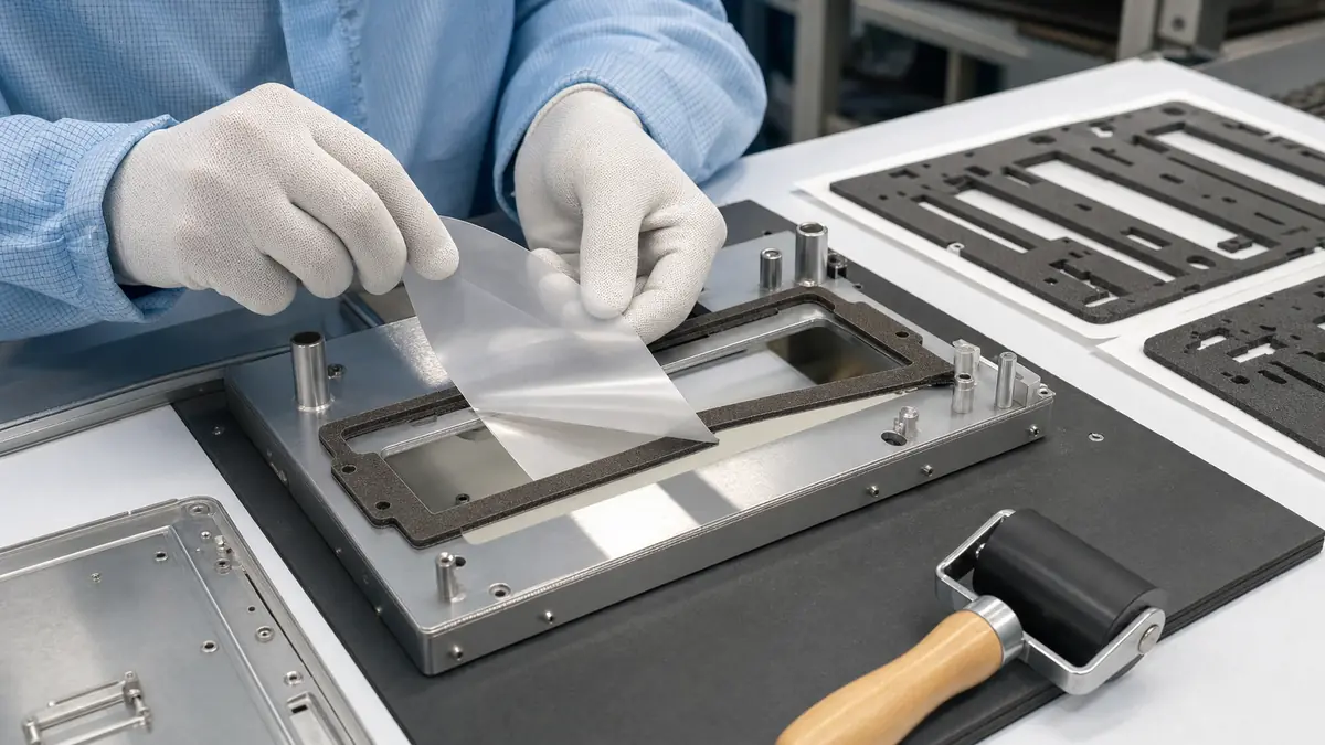
Industrial double-sided tape for EMI gasket lamination converts conductive foam, conductive fabric, elastomer, or composite gasketing into a placement-ready adhesive part. The adhesive must hold the gasket in its intended position without defeating the required electrical path, compression range, enclosure fit, corrosion plan, or rework method. Selection starts with the EMI design, not with peel strength alone.
Key Takeaways
- A pressure-sensitive adhesive can retain an EMI gasket during assembly, but retention and electrical performance are separate requirements.
- Use conductive adhesive only when the approved grounding path requires conductivity through the bond line.
- Gasket compression, housing finish, fastener pattern, adhesive thickness, and die-cut tolerance must be reviewed together.
- Shielding and grounding performance must be validated in the finished enclosure.
What Double-Sided Tape Does in an EMI Gasket Assembly
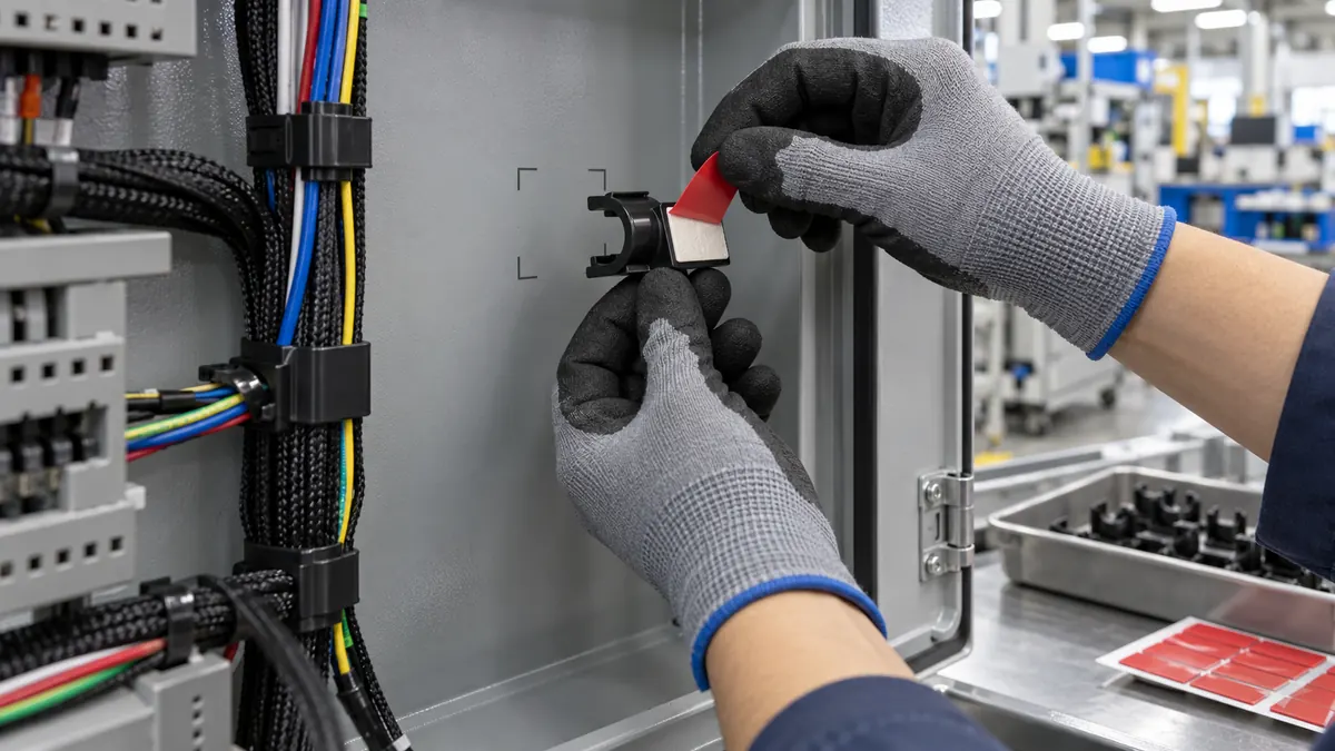
An EMI gasket closes a seam or gap between conductive enclosure surfaces so unwanted electromagnetic energy has a controlled shielding path. Depending on the design, the gasket may also fill a mechanical gap, accommodate tolerance, provide cushioning, or support an environmental seal. A pressure-sensitive adhesive layer can keep the gasket aligned during handling and final closure.
The adhesive is not automatically the shielding element. In some designs, the gasket makes electrical contact through an exposed face under compression while a non-conductive adhesive merely retains it on the opposite side. In other designs, conductivity through the adhesive bond line is required. The electrical engineer’s grounding and shielding plan must define which case applies.
Conductive vs Non-Conductive Double-Sided Adhesive
| Adhesive route | When it may be considered | Critical verification |
|---|---|---|
| Non-conductive transfer adhesive | The adhesive only positions the gasket and does not interrupt the designed contact path | Bond strength, thickness, edge squeeze, and confirmed electrical continuity elsewhere |
| Electrically conductive transfer tape | The bond line must carry current or form part of the shielding path | Contact resistance, substrate finish, corrosion compatibility, pressure, and frequency-specific performance |
| Double-coated conductive fabric tape | Flexible grounding or shielding attachment requires a conductive carrier | Cut-edge behavior, thickness, fabric stability, and shielding test results |
| Single-sided adhesive-backed gasket | One face is bonded for retention while the other contacts a mating flange | Compression range, recovery, exposed-face conductivity, and assembly closure |
| Gasket with no PSA | Grooves, clips, fasteners, or molded retention provide positioning | Assembly labor, retention, compression control, and service access |
EMI Gasket Data Required Before Tape Selection
| Design input | Record it as | Why it matters |
|---|---|---|
| Gasket material | Conductive foam, fabric-over-foam, filled elastomer, mesh, or composite | Controls surface energy, compressibility, cutting, and electrical path |
| Gasket dimensions | Width, thickness, corner radius, and tolerance in mm | Defines available bonding area and converted-part stability |
| Installed gap | Minimum and maximum enclosure gap in mm | Determines the actual compression range |
| Closure system | Fastener pitch in mm, torque specification, clips, or snap features | Influences compression uniformity and contact pressure |
| Housing surfaces | Metal or plated alloy, coating, paint, texture, and cleanliness | Affects adhesion, electrical contact, and galvanic compatibility |
| Electrical target | Grounding path, contact-resistance limit, and shielding test method | Determines whether the adhesive must conduct |
| Environment | Temperature in °C, humidity, fluids, vibration, and service life | Must be considered for both bond durability and gasket performance |
| Assembly format | Piece, sheet, roll, kiss-cut carrier, tab, and liner orientation | Controls operator handling and automation compatibility |
Adhesive and Liner Selection Factors
Bond to the gasket, not only the housing
Conductive foams and fabric surfaces can be porous, textured, or easily deformed. The adhesive must wet out the gasket without flooding cut edges or stiffening the compression zone. Test lamination peel from both the gasket and the housing after the intended dwell and environmental sequence.
Keep the adhesive inside the functional footprint
Adhesive squeeze-out can collect contamination, interfere with a contact edge, or change the effective gasket width. Die-cut the adhesive to a controlled offset where required and specify whether holes, tabs, and notches pass through the adhesive layer.
Use a stable liner for narrow or complex parts
A release liner is part of the assembly system. Polyester liners can provide dimensional stability for precision cutting and automated dispensing; paper liners may offer different tear and handling behavior. Split liners, extended tabs, and kiss-cut carriers can improve placement without touching the adhesive.
Consider rework before locking the material
Some enclosures are opened during repair, while others are treated as one-time assemblies. Define whether the gasket must be removed intact, replaced after opening, or cleaned from the flange. Rework needs can change adhesive strength, liner design, and part presentation.
Recommended Lamination and Die-Cutting Workflow
- Confirm the approved gasket orientation. Identify the housing side, mating-contact side, grain or fabric direction, and any conductive face.
- Condition and clean the materials. Follow the material owner’s contamination controls and keep particles away from the conductive surface.
- Laminate with controlled nip pressure. Avoid crushing the foam or driving adhesive into functional contact areas.
- Allow the specified dwell. Do not judge final adhesion immediately if the approved adhesive requires time to build contact.
- Die-cut to the controlled drawing. Manage adhesive offset, through-cuts, kiss-cuts, scrap matrix, and minimum web width.
- Inspect cut edges and liner release. Look for delamination, frayed fabric, compressed foam, adhesive strings, particles, and distorted holes.
- Package to prevent compression. Trays, sheets, or rolls should not permanently deform the gasket before assembly.
- Install on the enclosure datum. Use features or fixtures that control placement relative to seams, fasteners, vents, and connector openings.
Production Validation Checklist
| Validation area | Questions to answer | Evidence to retain |
|---|---|---|
| Adhesive retention | Does the gasket stay aligned through handling, closure, aging, and service? | Peel or retention method, condition, dwell, and failure mode |
| Compression | Is the gasket within its approved compression range across the enclosure? | Gap measurements, closure data, and witness inspection |
| Electrical path | Does the assembled bond line meet the grounding or resistance requirement? | Defined test method and measured results |
| Shielding | Does the complete enclosure meet the applicable EMI/EMC requirement? | Frequency range, fixture, enclosure state, and report |
| Environment | Do temperature, humidity, vibration, fluids, and corrosion alter performance? | Pre/post exposure comparison and visual evidence |
| Rework | Can the enclosure be opened and restored according to the service plan? | Removal procedure, residue check, and replacement rule |
Common Failure Modes
- Gasket shifts during closure: review surface preparation, liner-removal sequence, placement fixture, and initial tack.
- Adhesive peels from conductive foam: check surface texture, lamination pressure, adhesive wet-out, and material compatibility.
- Contact resistance is too high: verify whether a non-conductive adhesive blocks the intended path, then review pressure and housing finish.
- EMI result varies by unit: inspect compression uniformity, fastener spacing, gasket gaps, corners, seams, and placement tolerance.
- Adhesive squeezes into the seam: reduce uncontrolled overlap, correct the die-cut offset, and review compression and adhesive coat weight.
- Parts deform on the liner: improve carrier stability, web geometry, packaging, and release balance.
Related Products and Articles
- Compare industrial double-sided tape constructions for lamination and converted parts.
- Review conductive copper and fabric shielding tape options when the electrical path requires a conductive material.
- See custom die-cutting capabilities for gasket, foam, and adhesive parts.
- Read the custom die-cut tape guide for precision assembly.
- Send your gasket stack and enclosure drawing for material-format review.
Technical References
- 3M EMI shielding gasket tape guidance distinguishes single-sided and double-coated conductive gasket constructions and their grounding role.
- Parker Chomerics Conductive Elastomer Engineering Handbook describes pressure-sensitive adhesive as one of several EMI gasket mounting choices.
Frequently Asked Questions
Does EMI gasket adhesive have to be electrically conductive?
No. A non-conductive PSA may be acceptable when it only retains the gasket and the approved electrical path is established elsewhere. Use conductive adhesive when conductivity through the bond line is a design requirement.
Can ordinary double-sided tape be used on conductive foam?
Only after compatibility and electrical-path review. The tape must bond to the foam, survive the environment, stay within the thickness budget, and avoid blocking required grounding or shielding contact.
Should the adhesive cover the full gasket width?
Not always. Full coverage may simplify lamination, but an offset can prevent squeeze-out or preserve a contact area. The drawing should define adhesive coverage, exposed edges, holes, and tabs.
How is an adhesive-backed EMI gasket approved?
Approve the complete enclosure assembly. Check retention, compression, contact resistance, shielding performance, environmental durability, corrosion compatibility, placement tolerance, and the planned rework procedure.
Can EMI gaskets be supplied as kiss-cut parts on a liner?
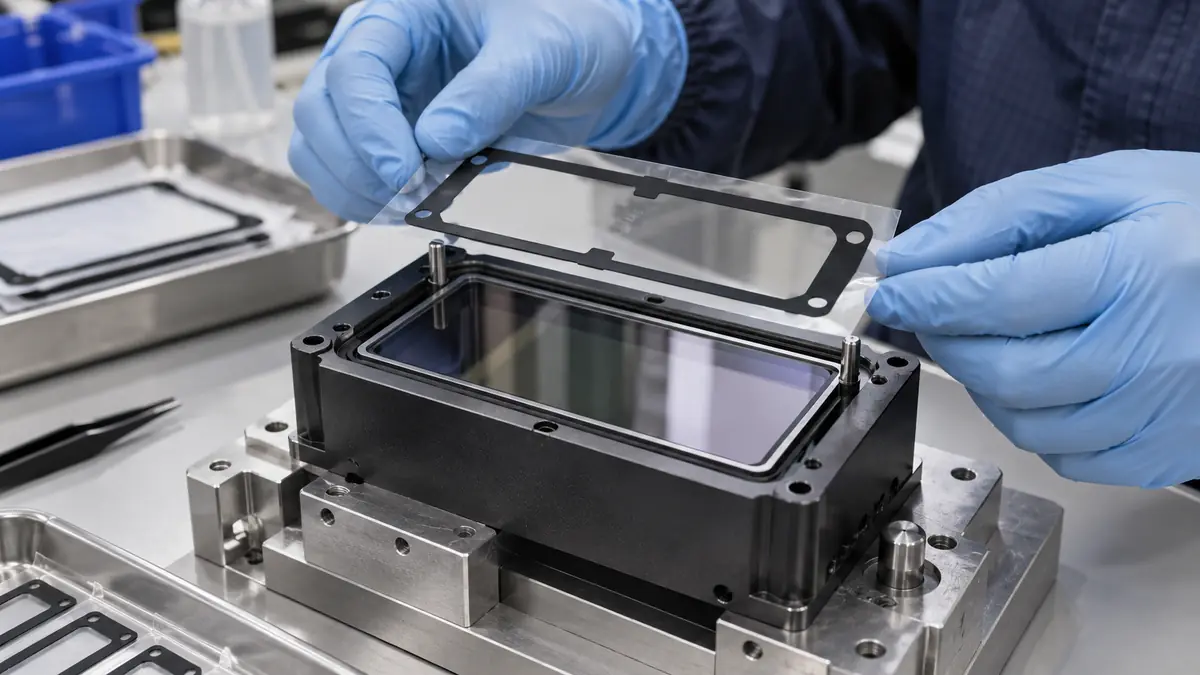
Yes. Kiss-cut presentation can improve handling and placement for repeated geometries. Liner material, release balance, part spacing, pull tabs, and packaging should match manual or automated assembly.
Develop an Adhesive-Backed EMI Gasket
Share the gasket material, adhesive function, enclosure surfaces, installed gap, compression range, electrical requirement, environmental exposure, drawing, annual quantity, and assembly presentation. JIAO TAO TAO can help compare double-sided adhesive and die-cut formats for your own validation program.
Industrial Double-Sided Tape for Touchscreen Bezel Bonding
Industrial Double-Sided Tape for Membrane Switch Assembly
Related Article
Need help choosing the right industrial tape?
Send us your application details, including temperature, surface material, size, quantity and current problem. Our team will help recommend a suitable tape material or custom die-cut solution.

simon@jiaotaotao.com


+86-136 1277 5969


+86-136 1277 5969
