
Custom Die-Cut Tape for Power Electronics Thermal Pad Positioning
Application Solutions · Power Electronics
Custom Die-Cut Tape for Power Electronics Thermal Pad Positioning
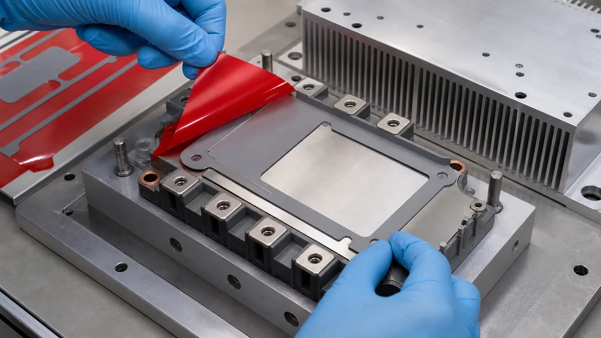
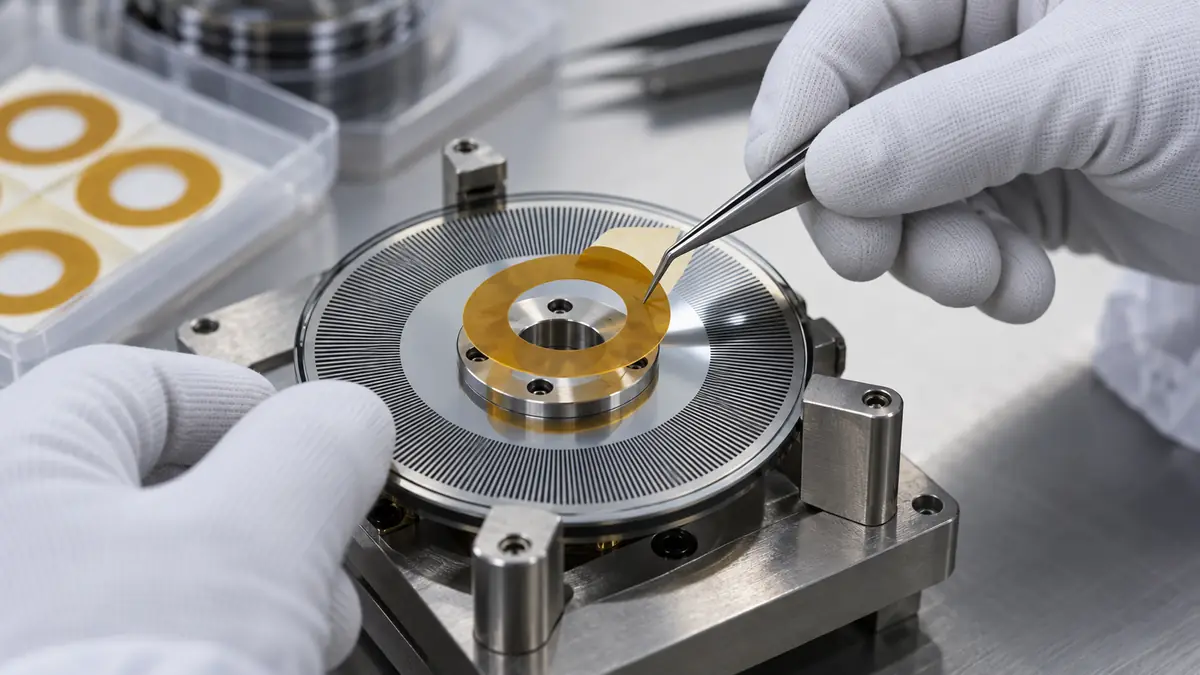
Custom die-cut tape for power electronics thermal pad positioning can help locate a compliant interface pad on a power module or heat-sink assembly before final clamping. The positioning feature must stay outside the active heat-transfer area unless the complete thermal stack has been specifically designed and tested to include it.
Quick Answer
A custom die-cut adhesive carrier, perimeter frame, pull-tab feature, or separate positioning patch can keep a thermal interface pad registered to an IGBT module, converter baseplate, heat spreader, or heat sink before fasteners apply the designed compression. The adhesive should not be placed through the active thermal area merely for convenience. Any material in the heat path changes thickness, contact, thermal resistance, and long-term behavior.
Define the Positioning Feature’s Role
Thermal pads bridge controlled surface variation and conduct heat between power components and cooling hardware. During assembly they can shift, fold, collect contamination, or remain attached to the wrong liner. A converted positioning feature may improve handling, but it must not reduce pad coverage over the intended heat source, block mounting holes, enter high-voltage keep-outs, or prevent the pad from conforming under clamp load.
| Positioning format | Possible use | Main limitation |
|---|---|---|
| Perimeter adhesive frame | Locates the pad around an approved outer margin | Must remain outside the qualified heat-transfer zone |
| Small edge tabs | Temporarily retain corners during handling | Tab thickness and peel access require control |
| Carrier liner with registration holes | Places a non-adhesive pad from fixture pins | All carrier material must be removed before closure |
| Pad with adhesive border | Combines pad and positioning function | Needs supplier-defined thermal and aging data for that construction |
| Separate fixture-only tape | Holds the pad in a nest outside the final joint | Must not contaminate or distort the pad |
Select Materials from the Complete Stack
Start with the thermal pad
Record pad material, thickness, hardness or compliance, surface tack, reinforcement, electrical function, storage, and permitted compression. Some pads are naturally tacky, while others require a liner or fixture for handling. Do not add an adhesive layer until the thermal-material supplier and assembly owner have reviewed the proposed interface.
Match the positioning adhesive to approved surfaces
A positioning feature may contact anodized or bare aluminum, nickel-plated copper, molded module housing, coated steel, or a pad surface. Screen adhesion and compatibility on the exact production finishes. The adhesive should survive storage and assembly without migrating into the thermal area or leaving contamination if it is removed.
Control voltage and cleanliness boundaries
Power modules can combine high-voltage terminals, grounded heat sinks, insulated baseplates, sensors, and sensitive contact surfaces. The electrical design owner must define creepage, clearance, dielectric, grounding, and contamination requirements. A generic die-cut tape must not be credited as an insulation barrier without qualification.
| Selection input | What to record | Why it matters |
|---|---|---|
| Thermal pad | Material, thickness, compliance, tack, and compression range | Defines the primary interface behavior |
| Contact surfaces | Module baseplate, heat sink, coatings, roughness, and flatness | Controls contact, adhesion, and cleanliness |
| Thermal load | Power loss, heat flux, temperature cycles, and cooling method | Shapes complete-assembly validation |
| Mechanical stack | Fasteners, pressure map, gap, tolerances, and vibration | Determines pad compression and retention |
| Conversion | Profile, holes, keep-outs, liner, tabs, pitch, and packaging | Turns the concept into a repeatable part |
Design Geometry, Liners, and Datums
Build the die-cut drawing from released module and heat-sink CAD. Define the active thermal footprint, minimum pad coverage, mounting holes, locating pins, terminal and voltage keep-outs, coolant or vent features, and any forbidden adhesive zone. Add tolerances for the pad itself, the converted positioning part, fixture, and module placement.
Split liners and extended pull tabs can let an operator expose only a positioning rail while protecting the pad surface from fingerprints and particles. Registration holes or asymmetric tabs prevent rotation. Liner color and stiffness can support poka-yoke, but every removable liner must have a positive inspection point so it cannot be trapped in the final stack.
Recommended Assembly Workflow
- Verify revisions. Match module, pad, heat sink, die cut, fixture, and work instruction.
- Condition materials. Follow pad and adhesive storage, thawing, and handling requirements.
- Inspect surfaces. Reject burrs, chips, oil, oxidation, damaged coating, or foreign material.
- Load the fixture. Support the module without stressing terminals or baseplate.
- Expose the first liner zone. Keep the thermal-pad face protected during alignment.
- Register the die cut. Use pins, edges, holes, or vision features from the drawing.
- Apply controlled pressure. Seat only the approved positioning adhesive area.
- Remove all final liners. Confirm each liner and tab is accounted for.
- Close the stack. Place the heat sink squarely and tighten in the released sequence.
- Inspect and record. Verify pad coverage, fasteners, cleanliness, and traceability.
Qualification and Production Validation
Evaluate the hottest credible operating point, lowest and highest pad compression, flatness and roughness limits, multiple assembly operators, and realistic storage age. Compare the positioned assembly with the baseline thermal interface specified by the module or system owner. A convenient assembly method is not acceptable if it changes thermal or electrical performance.
- Measure pad location, coverage, wrinkles, trapped air, edge damage, and final compression where possible.
- Map temperatures or thermal performance using the product owner’s approved instrumentation and loading method.
- Run required power cycling, thermal cycling, vibration, humidity, dielectric, insulation, and functional tests.
- Inspect the stack after conditioning for adhesive migration, pad pump-out, cracking, delamination, or residue.
- Requalify changes to pad, adhesive, liner, heat sink, coating, fixture, torque, or mounting sequence.
Troubleshooting Common Defects
| Observed defect | Check first | Corrective direction |
|---|---|---|
| Pad shifts during heat-sink placement | Initial retention, liner removal, fixture datum, and closing direction | Revise tab/frame geometry or temporary support |
| Pad wrinkles or folds | Carrier release, handling path, edge tack, and placement angle | Use staged liner removal and a flatter placement method |
| Unexpected temperature rise | Pad coverage, thickness stack, trapped liner, compression, and surface | Stop and audit the complete thermal interface |
| Adhesive enters the active area | Die-cut tolerance, squeeze-out, heat, and pressure | Increase keep-out and requalify the construction |
| Liner remains in the assembly | Tab visibility, count, work sequence, and inspection | Add positive liner-accountability controls |
Related Products and Articles
Frequently Asked Questions
Can ordinary double-sided tape be placed under a thermal pad?
Not without thermal-stack approval. An added adhesive layer changes thickness, contact, thermal resistance, aging, and electrical behavior. Keep positioning adhesive outside the active area unless qualified.
When is a carrier liner better than adhesive tabs?
A registration carrier can position a non-adhesive pad without leaving material in the joint. It needs clear pull tabs, controlled release, and positive confirmation that the full carrier was removed.
Can the die cut also provide electrical insulation?
Only if the released construction, geometry, voltage boundary, aging, and complete assembly tests support that function. Do not infer insulation performance from film color or thickness alone.
How should pad alignment be inspected?
Use visible datums, fixture or camera checks, exposed witness features, or another method defined by the assembly owner. Verify minimum thermal-area coverage and all keep-outs.
What belongs in an RFQ?
Provide module, pad, and heat-sink drawings; surfaces; thermal and voltage requirements; compression; keep-outs; liner concept; placement method; tolerances; volume; and validation plan.
Turn the Thermal Pad into an Assembly-Ready Part
Share the power-module footprint, pad construction, active thermal zone, voltage keep-outs, heat-sink surface, compression stack, liner preference, placement tolerance, and volume. JIAO TAO TAO can help prototype a die-cut positioning format for qualification.
Discuss thermal-pad positioningCustom Die-Cut Tape for Industrial Barcode Scanner Window Bonding
PET Silicone Tape for Threaded Insert Masking During Powder Coating
Related Article
Need help choosing the right industrial tape?
Send us your application details, including temperature, surface material, size, quantity and current problem. Our team will help recommend a suitable tape material or custom die-cut solution.

simon@jiaotaotao.com


+86-136 1277 5969


+86-136 1277 5969
