
Custom Die-Cut Tape for LCD Backlight Light-Leak Control
Custom Die-Cut Tape for LCD Backlight Light-Leak Control
Custom die-cut tape for LCD backlight assembly creates a repeatable light-blocking border around optical layers, frames, bezels, and display openings. A successful part must do more than look black: the material, adhesive, geometry, liner, registration method, compression, and optical inspection standard must work together in the finished module.
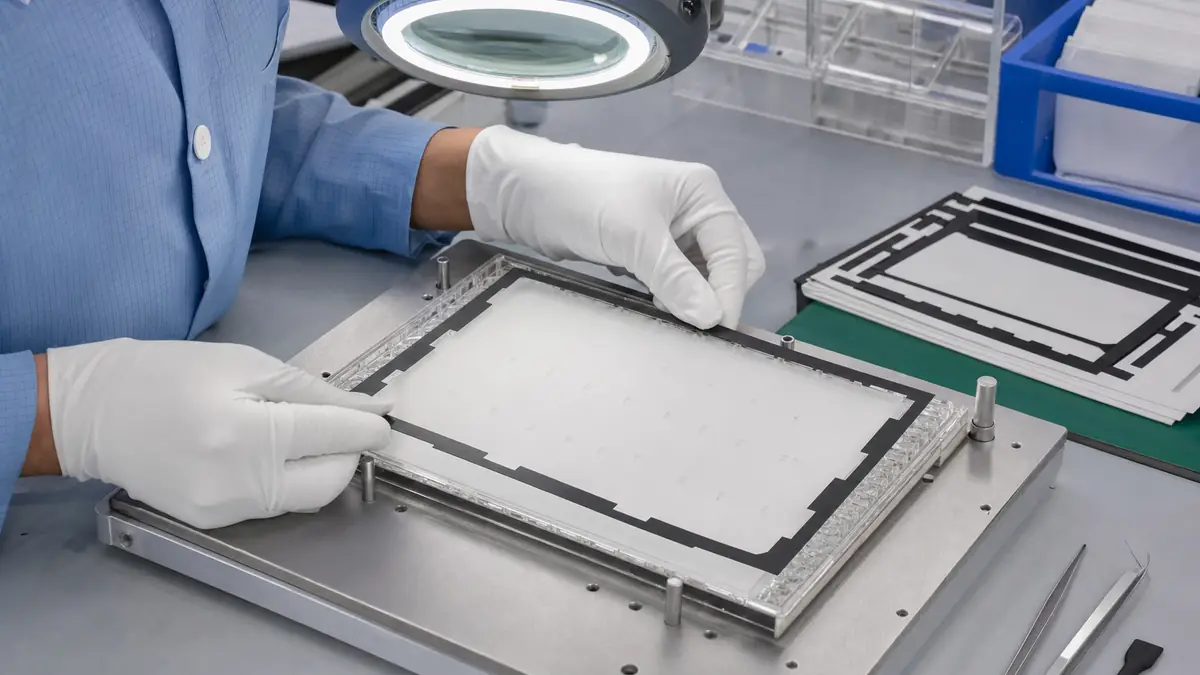
Why LCD Backlights Need a Converted Tape Part
An LCD backlight contains multiple optical and mechanical interfaces. Light can escape where a film edge, light guide, reflector, bezel, housing, or display opening is not covered consistently. Hand-cut tape may correct a prototype, but variable width, uneven corners, excessive overlap, and exposed gaps make the result difficult to repeat in production.
A kiss-cut frame or segmented die-cut set can place a controlled light-blocking boundary around the active area. Registration holes, corner radii, pull tabs, and a stable carrier liner can also reduce handling and help operators position the part without touching the adhesive.
Define the Light-Leak Path Before Selecting Tape
Start with the location of the optical defect rather than a generic request for “black tape.” Inspect the module in the intended dark-room or low-light condition and identify whether leakage originates at the outer perimeter, a connector opening, a housing seam, a corner, a reflective surface, or a stack-height transition. The corrective part must cover the path without intruding into the visible area or loading sensitive optical films.
Perimeter light blocking
A thin, dimensionally stable film construction can form a defined border where the assembly has limited z-height. The drawing should specify inner-window dimensions, outer dimensions, corner radii, and the relationship to the active display area.
Gap filling and compression
Where a mechanical gap varies, a compressible construction may be considered. Compression must be controlled so the material does not distort the light guide, create mura, lift a bezel, or change the display stack.
Selection Parameters for a Die-Cut Backlight Tape
| Parameter | Why it matters | What to verify on the module |
|---|---|---|
| Opacity and surface reflectance | Controls light transmission and unwanted internal reflection | Does the part block the identified leak under the approved inspection condition? |
| Total thickness | Affects stack height, bezel fit, and local pressure | Does the assembled display remain flat and free from optical distortion? |
| Adhesion to each substrate | The part may contact metal, coated plastic, glass, or optical film | Does the edge stay down after aging and assembly handling? |
| Dimensional stability | Protects the inner window and registration relationship | Does the die-cut frame retain its shape during liner removal and placement? |
| Cleanliness and converting quality | Loose fibers, particles, and adhesive squeeze can affect an optical assembly | Are cut edges clean and compatible with the production cleanliness requirement? |
| Liner release and presentation | Influences pick-up, placement speed, and adhesive handling | Can operators or equipment remove the part without stretching or curling it? |
Comparing Common Light-Control Constructions
| Construction | Useful characteristics | Design cautions |
|---|---|---|
| Black film tape | Thin profile, defined edge, good shape retention | Confirm opacity, reflectance, stiffness, and adhesion to the real substrates |
| Black double-sided film adhesive | Combines light blocking with layer-to-frame bonding | Control adhesive squeeze, window tolerance, and rework method |
| Black foam tape or gasket | Can fill a controlled gap and accommodate surface variation | Verify compression, recovery, particle control, and effect on optical uniformity |
| Segmented die-cut strips | May simplify placement around connectors or interrupted geometry | Joints and corners must not create new light paths |
Geometry, Tolerances, and Liner Design
Protect the visible window
The inner cutout should be referenced to functional display datums, not only to the outside of a loose tape part. Include an optical keep-out margin that accounts for part tolerance, display tolerance, placement capability, and any material movement during lamination.
Avoid weak webs and sharp inside corners
Very narrow webs can stretch, fold, or remain on the waste matrix. Practical corner radii and bridge widths improve converting and handling. If the shape cannot be delivered reliably as one frame, a controlled segmented layout may be more robust.
Use the liner as an assembly tool
A split liner, extended pull tab, transparent placement carrier, or registration holes can make a precise part easier to apply. The liner plan should match the actual sequence: fixture loading, partial liner removal, alignment, lamination, and carrier removal.
Recommended Assembly Workflow
- Clean and inspect the bonding surfaces. Use the display maker's approved cleaning method and prevent lint or fingerprints from entering the optical stack.
- Locate the module in a repeatable fixture. Reference functional datums that also appear on the die-cut drawing.
- Remove only the planned liner section. Keep the adhesive protected until alignment is established.
- Place without stretching. Lower the frame progressively and prevent the inner window from drifting toward the active area.
- Laminate with controlled pressure. Press the complete perimeter while avoiding point loads on optical layers.
- Inspect corners, joints, and openings. Look for lifting, wrinkles, contamination, adhesive squeeze, and uncovered light paths.
- Perform the approved optical check. Evaluate the assembled module at the specified brightness, viewing angle, and ambient-light condition.
Prototype and Production Approval
Approve the construction with production-representative substrates, the final bezel and housing, the real lamination method, and the intended environmental sequence. Check light leakage, luminance uniformity, visible-area intrusion, adhesive lift, liner handling, contamination, compression set where relevant, and disassembly behavior. Record the approved material code, drawing revision, liner format, and inspection method to prevent unreviewed substitutions.
Related Tape Resources
- Review available custom die-cutting solutions for precision adhesive parts.
- Read what custom die-cut adhesive is and how converted formats support repeatable assembly.
- Send your display stack and die-cut drawing for material and presentation-format review.
Frequently Asked Questions
Is any black tape suitable for LCD backlight light blocking?
No. Color alone does not prove opacity, low reflectance, cleanliness, adhesion, dimensional stability, or compatibility with optical films. Evaluate the complete tape construction in the final module.
Should the light-blocking frame be one piece or several strips?
A one-piece frame can improve registration and corner continuity, while segmented strips may be easier around interrupted geometry. Compare placement capability, joint design, web strength, and material utilization.
Can thicker foam always solve a backlight edge gap?
No. Extra thickness or compression can load optical layers and change display uniformity. Measure the real gap and validate compression in the assembled housing.
Why does a die-cut frame stretch during placement?
Possible causes include narrow webs, high liner release, an unstable carrier, poor pick-up technique, or excessive tension. A revised liner and application fixture may solve the problem without changing the base material.
What files are useful for a die-cut quotation?
Provide a dimensioned drawing, target material or functional requirements, substrate details, stack-height limit, tolerances, liner preference, quantity, and an image or description of the assembly sequence.
Develop a Light-Blocking Die-Cut for Your Display Module
Share the LCD backlight geometry, active-area keep-out, bonding substrates, gap or stack-height data, assembly method, optical inspection condition, and preferred sheet or roll presentation. The JIAO TAO TAO team can help compare tape constructions and prepare parts for your own module validation.
PTFE Tape for PVC Window Profile Welding Machines
PTFE Tape for Textile Fusing Press Platen Protection
Related Article

Need help choosing the right industrial tape?
Send us your application details, including temperature, surface material, size, quantity and current problem. Our team will help recommend a suitable tape material or custom die-cut solution.

simon@jiaotaotao.com


+86-136 1277 5969


+86-136 1277 5969
