
Custom Die-Cut Tape for Busbar Phase Isolation
Custom Die-Cut Tape for Busbar Phase Isolation
Custom die-cut insulation tape for busbar phase isolation converts a specified electrical-insulation material into ready-to-place parts that match copper geometry, bolt clearances and phase-separation zones. It can improve placement consistency and line efficiency, but the tape part must be engineered as one element of the cabinet’s complete insulation system. Material approval, electrical clearances and finished-assembly validation remain the responsibility of the equipment design team.
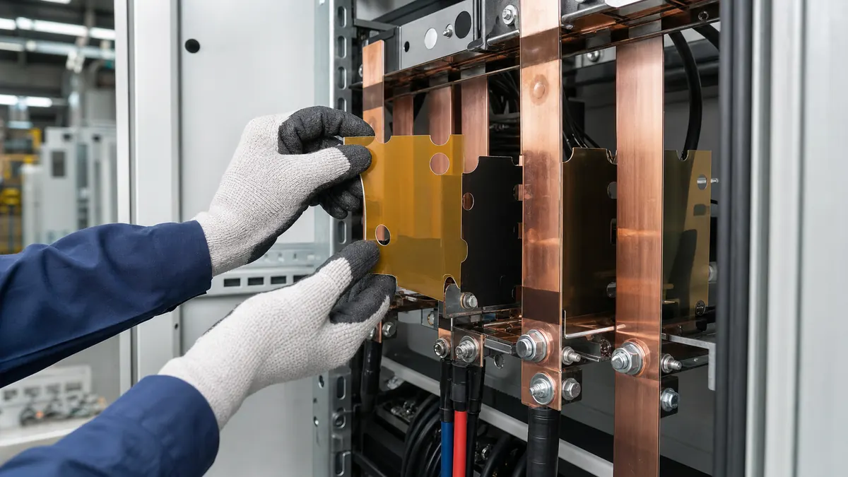
Why Busbar Insulation Benefits From a Die-Cut Format
Busbar compartments contain corners, holes, joint interfaces, supports and conductor transitions that are difficult to cover repeatably with hand-cut roll tape. Manual trimming can create variable overlap, exposed edges, liner waste and inconsistent assembly time. A kiss-cut part supplied on a stable liner gives operators a defined shape and orientation before the cabinet is closed.
Die cutting does not increase the electrical rating of the base material. Its practical value is geometric repeatability: the approved film, adhesive and thickness can be delivered in a format that fits the intended location with less line-side cutting.
Information to Include in the RFQ
| RFQ input | Details to provide | Why it matters |
|---|---|---|
| Geometry | 2D drawing, hole locations, radii, keep-out zones and revision level | Defines the cutting tool and prevents interference with hardware |
| Electrical function | Barrier, edge coverage, phase identification or localized surface insulation | Separates the part’s role from the complete insulation design |
| Substrate | Copper finish, plating, coating, nearby plastics and surface cleanliness | Adhesion can change with surface condition |
| Environment | Assembly temperature, service temperature, humidity and chemical exposure | Guides material and adhesive screening |
| Placement method | Manual, fixture-assisted or automated; target takt time | Controls liner, pitch, tabs and delivery format |
| Volume | Prototype quantity, annual demand and change frequency | Influences tooling and converting route |
Material Options to Compare
| Material direction | Useful characteristics | Questions before approval |
|---|---|---|
| Polyimide film tape | Thin electrical insulation and elevated-temperature capability | Is the selected thickness, adhesive and permanent-use condition qualified? |
| PET insulation film tape | Dimensional stability and economical conversion for moderate process windows | Does the actual thermal and electrical requirement fit the construction? |
| Cloth or reinforced tape | Conformability and mechanical protection around selected edges | Will the woven structure add too much thickness or absorb contamination? |
| Non-adhesive insulation film | Can form a defined barrier without pressure-sensitive adhesive | How will it be retained and controlled during assembly? |
Do not choose a part solely from a generic “high voltage” or “battery grade” description. Ask for construction-specific data and qualify the complete part on the intended conductor, cabinet geometry and manufacturing process.
Design the Liner and Part Together
Add handling features only where they help
Finger-lift tabs, split liners and extended release sections can reduce contact with the adhesive and improve alignment. They also consume space and may complicate the cutting layout. Review the actual operator hand position and fixture access before adding them.
Control narrow bridges and internal cutouts
Thin webs can stretch, fold or remain in the waste matrix. A converter may recommend minimum feature sizes, corner radii or a small geometry change to improve part release without changing the functional coverage zone.
Choose sheet or roll presentation by the station
Sheets are convenient for prototypes and low-volume manual work. Roll-fed kiss-cut parts can support higher-volume stations and automation, but pitch, unwind direction, core size and sensor marks must be specified.
Prototype and Validation Plan
- Freeze a drawing revision and identify the insulation material under evaluation.
- Cut a small prototype lot using production-representative liner and adhesive construction.
- Apply parts to busbars prepared with the real cleaning and handling process.
- Inspect edge coverage, wrinkles, trapped air, fastener clearance and interference with supports.
- Complete the cabinet’s required electrical, thermal and environmental validation; do not infer performance from flat coupons alone.
- Run an operator study for liner removal, placement time, misalignment and rework.
- Release the drawing, material code, delivery format and inspection criteria together.
Common Failure Modes
| Observed issue | Possible cause | What to review |
|---|---|---|
| Part shifts during placement | Liner release is too high or alignment feature is missing | Release balance, finger lift and fixture strategy |
| Edge lifts near a bend | Part bridges the geometry or surface contact is incomplete | Radius, material stiffness, cleaning and application pressure |
| Internal cutout stays with the part | Waste stripping is unstable | Feature size, tooling clearance and matrix design |
| Coverage varies after fastening | Hardware compresses or drags the tape | Assembly sequence and clearance around the joint |
| Operator installs the part backwards | Orientation is not obvious | Asymmetric poka-yoke geometry and liner presentation |
FAQ
Does die-cut tape replace required creepage and clearance?
No. A die-cut part can support localized insulation and controlled coverage, but the equipment designer must determine creepage, clearance and the complete insulation system for the applicable design.
Should the part wrap around a busbar edge?
That depends on the defined insulation zone, bend radius and selected material. Edge wrapping must be validated on the actual geometry because a stiff film can bridge or lift.
Can busbar insulation parts be supplied on a roll?
Yes. Roll-fed kiss-cut formats can support repeat placement when part pitch, unwind direction, liner and equipment interface are specified.
What is the best material for busbar phase isolation?
There is no universal best material. The choice depends on the electrical design, thickness limit, temperature, environment, substrate and qualification plan.
Related Products and Articles
- Die-cut and customized adhesive tape solutions
- Polyimide tape for die-cut insulation parts
- Non-conductive tape for battery equipment
- Custom die-cut tape for precision assembly
Request a Geometry-Based Sample
Send JIAO TAO TAO the busbar drawing, substrate finish, approved material direction, placement method, liner preference, prototype quantity and required delivery format. The converting team can review manufacturability and prepare parts for your controlled assembly and qualification process. Discuss your busbar insulation part.
Industrial Double-Sided Tape for Membrane Switch Assembly
Industrial Double-Sided Tape for Appliance Control Panel Bonding
Related Article

Need help choosing the right industrial tape?
Send us your application details, including temperature, surface material, size, quantity and current problem. Our team will help recommend a suitable tape material or custom die-cut solution.

simon@jiaotaotao.com


+86-136 1277 5969


+86-136 1277 5969
