
Acetate Cloth Tape for Relay Coil Wrapping and Insulation
Acetate Cloth Tape for Relay Coil Wrapping and Insulation
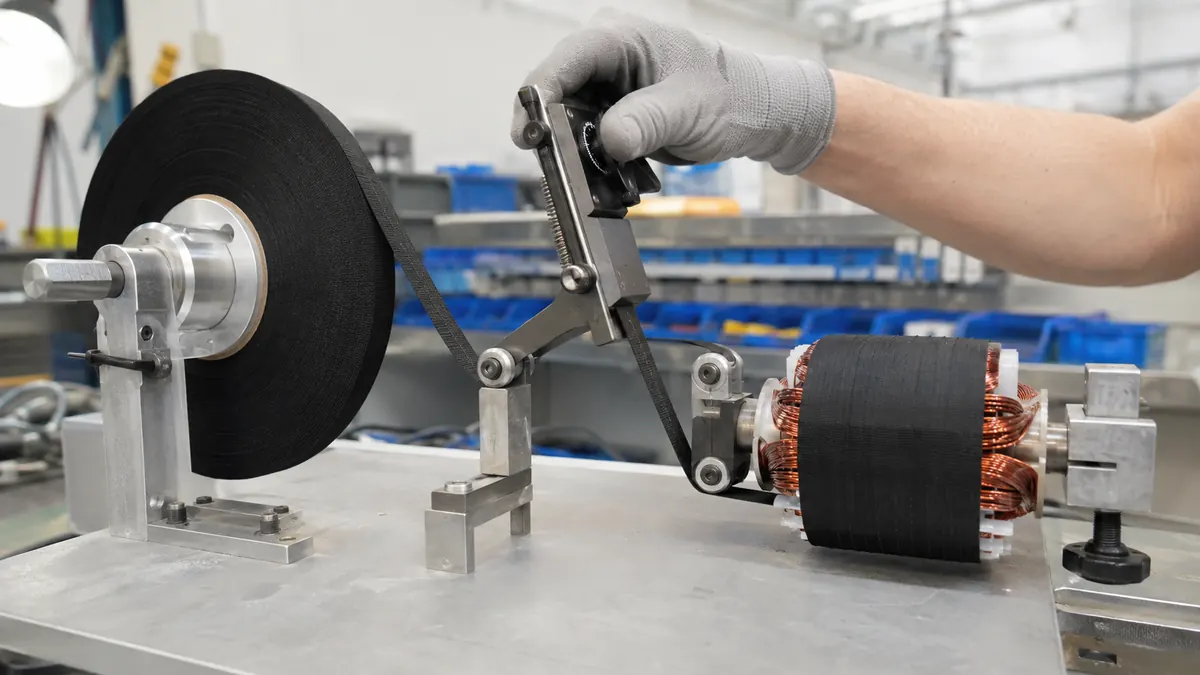
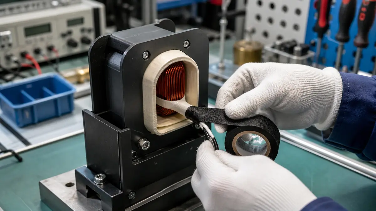
Acetate cloth tape for relay coil wrapping forms a conformable outer wrap around a wound bobbin, lead transition, or specified insulation detail. The cloth backing can follow compact coil geometry and resist handling abrasion, but suitability depends on the released relay design, insulation system, adhesive, wrap build, operating temperature, varnish or impregnation process, terminal clearance, and qualification plan.

Key Takeaways
- Use the relay’s released insulation system and coil drawing as the primary design authority.
- Control tape width, overlap, wrap count, start and finish positions, and terminal keep-out zones.
- Check compatibility with winding wire, bobbin, leads, varnish, potting, cleaning, and storage.
- Qualify the finished relay or contactor coil, not the tape roll alone.
What an Acetate Cloth Outer Wrap Can Do
Relay and contactor coils combine enamelled winding wire, a bobbin, terminals or lead wires, primary insulation details, and often a magnetic assembly or enclosure. An outer acetate cloth wrap may protect the winding surface during handling, hold a lead or start/finish wire in a defined position, cover a localized edge, improve wrap conformity, or support the approved insulation build.
The tape should not be treated as a universal replacement for bobbin walls, slot barriers, interlayer insulation, sleeving, varnish, potting, creepage and clearance, or other released components. Its function and boundary need to be explicit so that production does not add or remove wraps by judgment.
Relay-Coil Tape Functions Compared
| Wrap function | Possible benefit | Key risk to review |
|---|---|---|
| Outer winding protection | Reduces direct handling contact and abrasion on the exposed winding surface | Added build interferes with the magnetic frame, cover, or bobbin clearance |
| Lead anchoring | Holds a start, finish, or crossover lead in a controlled route | Tape edge creates a stress point or the lead moves during cure or assembly |
| Local edge coverage | Covers a defined transition near a bobbin flange or winding edge | Insufficient coverage, wrinkles, or adhesive flow reduces the intended barrier |
| Identification or appearance | Creates a consistent dark outer surface for inspection or assembly recognition | Color is mistaken for an electrical or thermal rating |
| Process holding aid | Temporarily holds the winding before impregnation, testing, or enclosure assembly | Compatibility with varnish, potting, cleaning, or removal has not been checked |
Data Required for Tape and Wrap Selection
| Parameter | Record it as | Why it matters |
|---|---|---|
| Relay or contactor design | Coil drawing, bobbin material, magnetic assembly, enclosure, and available clearance | Defines the mechanical space and interfaces around the wrap |
| Winding system | Wire type, enamel system, winding dimensions, lead route, and crossover locations | Controls surface compatibility and protection needs |
| Electrical requirement | Voltage, insulation coordination, dielectric tests, and applicable design rules | Sets the approval criteria for the completed component |
| Thermal exposure | Measured coil and tape temperatures, duty cycle, heat soak, and ambient range | Provides the real condition for tape screening |
| Post-wrap process | Impregnation, varnish, potting, cure, cleaning, soldering, and drying sequence | May change adhesion, swelling, residue, or material compatibility |
| Wrap specification | Tape width, total thickness, overlap, wrap count, tension, start, finish, and direction | Controls build, coverage, and process repeatability |
| Inspection plan | Coverage, wrinkles, gaps, terminals, lead position, dimensions, and traceability | Turns the wrap into a controlled manufacturing step |
How to Choose and Apply the Tape
Confirm compatibility with the insulation system
The cloth backing, pressure-sensitive adhesive, winding enamel, bobbin resin, sleeving, varnish, potting compound, and cleaning materials may contact one another during processing or service. Use supplier documentation to screen candidates, then test the actual material combination after the full cure and aging sequence.
Set width and overlap from the coil geometry
A tape that is too wide can wrinkle around a short bobbin or cover terminals and flange features. A narrow tape may require extra turns and create multiple overlap steps. Define the overlap as a controlled dimension or turn pattern, and include worst-case coil height and winding variation.
Control application tension
Excessive tension can compress or displace the outer winding, bow a thin flange, or move a lead. Too little tension may create a loose wrap or trapped folds. Establish a repeatable hand method, fixture, or wrapping-machine setting and verify the finished coil dimensions.
Protect terminal and magnetic clearances
Keep tape and adhesive outside released solder, weld, terminal, contact, sensor, and magnetic seating areas. The finish tail should not project into a frame, core, armature, or enclosure interface. Use a visual datum or fixture stop rather than estimating the finish position.
Recommended Relay-Coil Wrapping Workflow
- Review the released coil drawing. Identify winding boundaries, leads, terminals, flanges, magnetic interfaces, and tape keep-out zones.
- Inspect the wound bobbin. Reject damaged enamel, loose wire, incorrect lead routing, contamination, or out-of-tolerance winding build according to the process plan.
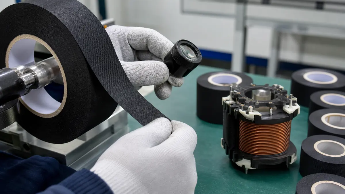
- Prepare the correct tape format. Confirm grade, width, roll condition, storage history, and any pre-cut length.
- Anchor at the specified datum. Begin on the approved face and direction without placing the start edge over a sensitive lead transition.
- Wrap with controlled tension and overlap. Smooth the cloth around the coil without wrinkles, gaps, excessive stretching, or trapped debris.
- Finish inside the released zone. Press the tail completely and verify terminals, leads, flanges, and magnetic surfaces remain clear.
- Run downstream processes. Apply the approved varnish, cure, potting, soldering, cleaning, or assembly sequence without unreviewed substitutions.
- Inspect and test the completed component. Verify dimensions, coverage, lead position, electrical tests, thermal behavior, mechanical fit, and aging results.
Troubleshooting and Qualification Checks
| Observed issue | Tape checks | Process/design checks |
|---|---|---|
| Wrap lifts at the tail | Adhesive compatibility, overlap, storage, roll condition, and finish pressure | Surface contamination, tension, cure exposure, and finish location |
| Cloth wrinkles around the bobbin | Tape width, backing conformity, thickness, and edge quality | Wrap angle, tension, bobbin geometry, and winding variation |
| Lead moves or breaks | Tape edge position, stiffness, adhesive grab, and wrap sequence | Lead routing, strain relief, pull load, soldering, vibration, and assembly handling |
| Coil no longer fits the frame | Total tape build, overlap count, tail stack, and thickness tolerance | Winding dimensions, bobbin distortion, frame clearance, and fixture setup |
| Appearance changes after varnish or cure | Backing and adhesive compatibility, absorption, color, and exposure limit | Varnish chemistry, cure profile, drainage, cleaning, and storage |
Qualification may include the organization’s dimensional, dielectric, insulation-resistance, thermal-rise, cycling, vibration, humidity, fluid, cure, pull, and life tests as applicable. Test methods and acceptance limits come from the relay design and its governing requirements, not from a generic tape article.
Related Products and Articles
- Explore the acetate cloth tape product range.
- Review common acetate cloth tape uses and selection factors.
- Compare heat-resistant electrical insulation options in the polyimide tape product guide.
- Send the coil drawing, materials, process, and test requirements for a tape review.
Frequently Asked Questions
Why is acetate cloth tape used on relay coils?
Its woven backing can conform around a wound bobbin and provide handling protection, lead control, local coverage, or part of an approved insulation detail. The finished component still requires design-specific qualification.
How many layers of acetate tape should wrap a relay coil?
There is no universal layer count. Define the required coverage, overlap, total build, clearance, insulation function, and test results in the released drawing and process specification.
Can acetate cloth tape contact enamelled winding wire?
Only after compatibility is established for the exact wire enamel, tape adhesive, temperature, varnish or potting chemistry, cure, and aging sequence. Similar-looking materials may behave differently.
Can the wrapped coil be varnish impregnated?
It may be possible in an approved system, but the tape must be evaluated for varnish wetting, absorption, swelling, adhesion, cure exposure, drainage, and the completed relay’s electrical and mechanical results.
What should an acetate tape RFQ include?
Include the coil and bobbin drawing, winding and lead materials, electrical and thermal requirements, post-wrap processing, tape width, overlap, quantity, packaging, and qualification plan.
Prepare a Relay-Coil Wrapping Trial
Share the relay or contactor coil drawing, bobbin and wire materials, lead route, available clearance, measured thermal duty, varnish or potting process, wrap pattern, annual quantity, and acceptance tests. JIAO TAO TAO can help shortlist an acetate cloth tape format for your own component validation.
Contact the technical team about your relay-coil insulation project.
Acetate Cloth Tape for Toroidal Transformer Core Wrapping
Double-Sided Polyimide Tape for FPC Stiffener Bonding
Related Article
Need help choosing the right industrial tape?
Send us your application details, including temperature, surface material, size, quantity and current problem. Our team will help recommend a suitable tape material or custom die-cut solution.

simon@jiaotaotao.com


+86-136 1277 5969


+86-136 1277 5969
