
Custom Die-Cut Tape for Pressure Sensor Port Masking
Custom Die-Cut Tape for Pressure Sensor Port Masking
Custom die-cut tape for pressure sensor port masking protects a defined opening, reference surface, or no-coat zone during conformal coating, painting, potting, cleaning, and other assembly processes. A pre-cut ring or tab can improve placement repeatability compared with trimming roll tape beside a small sensing port. The mask still has to match the real housing, process chemistry, edge tolerance, dwell time, and removal method.

Key Takeaways
- Define the functional opening, keep-out boundary, exposed datum, and acceptable coating edge on a controlled drawing.
- Select the tape construction from the complete process, not from the word “sensor.”
- Use a liner, pull tab, and orientation feature that support repeatable handling without touching the adhesive.
- Inspect both mask placement before processing and port condition after removal.
- Qualify representative housings, contamination levels, chemistry, cure, dwell, and removal conditions before production release.
What Pressure Sensor Port Masking Must Control
A pressure sensor may use a small port, threaded passage, diaphragm opening, reference vent, or capillary path to communicate with the measured medium. Coating, sealant, blasting debris, cleaning fluid, or assembly contamination in that path can alter the finished component. A temporary mask creates a controlled process boundary while allowing the surrounding housing or circuit assembly to receive the required treatment.
The masking drawing should separate three zones: the opening that must remain clear, the land where the adhesive may contact the part, and the surrounding surface that may be coated. The adhesive ring must not bridge into the functional port. It also must not cover a datum, sealing face, laser mark, connector feature, or grounding area unless that coverage is specifically approved.
Die-Cut Mask Formats Compared
| Format | Potential fit | Main control point |
|---|---|---|
| Kiss-cut ring on liner | Round ports with a defined exposed center | Inside diameter, concentricity, liner release, and edge seal |
| Disc with pull tab | Temporary coverage over an opening or flat seat | Tab direction, removal access, and no adhesive intrusion |
| Keyed custom shape | Ports beside connectors, ribs, screws, or asymmetric features | Orientation, drawing datum, and operator error-proofing |
| Carrier strip with multiple masks | Repeated manual or semi-automatic placement | Pitch, presentation, liner stiffness, and part count |
| Hand-cut roll tape | Early trials or very simple, low-volume geometry | Variable edges, contamination, trimming risk, and labor |
Information Required Before Designing the Die-Cut
| Input | What to document | Why it matters |
|---|---|---|
| Sensor geometry | Port diameter, land width, ribs, curvature, roughness, sealing face, and drawing revision | Defines the mask shape and available adhesive contact area |
| Process route | Cleaning, coating, cure, potting, painting, rinsing, drying, and handling sequence | The mask encounters every stage, not only the main coating step |
| Process materials | Coating, solvents, cleaners, release agents, sealants, and incidental fluids | Film and adhesive compatibility must be screened |
| Thermal exposure | Actual part temperature, heating and cooling rate, dwell, and repeat cycles | Controls dimensional stability, adhesion, and removal behavior |
| Placement requirement | Datum, allowed offset, edge tolerance, orientation, and inspection method | Turns the drawing into a measurable application standard |
| Delivery format | Sheet, roll, pitch, liner, tab, waste matrix, quantity, and application equipment | Determines handling efficiency and converting design |
Choose the Adhesive Land Before the Mask Diameter
A larger ring may provide more contact area, but it can also cover a sealing surface or create an unacceptable coating shadow. A narrow ring saves space but may not tolerate surface texture, curvature, or process flow. Build the mask from the functional keep-out zone outward, then confirm that the remaining adhesive land is continuous and accessible for burnishing.
Use the Liner as Part of the Application System
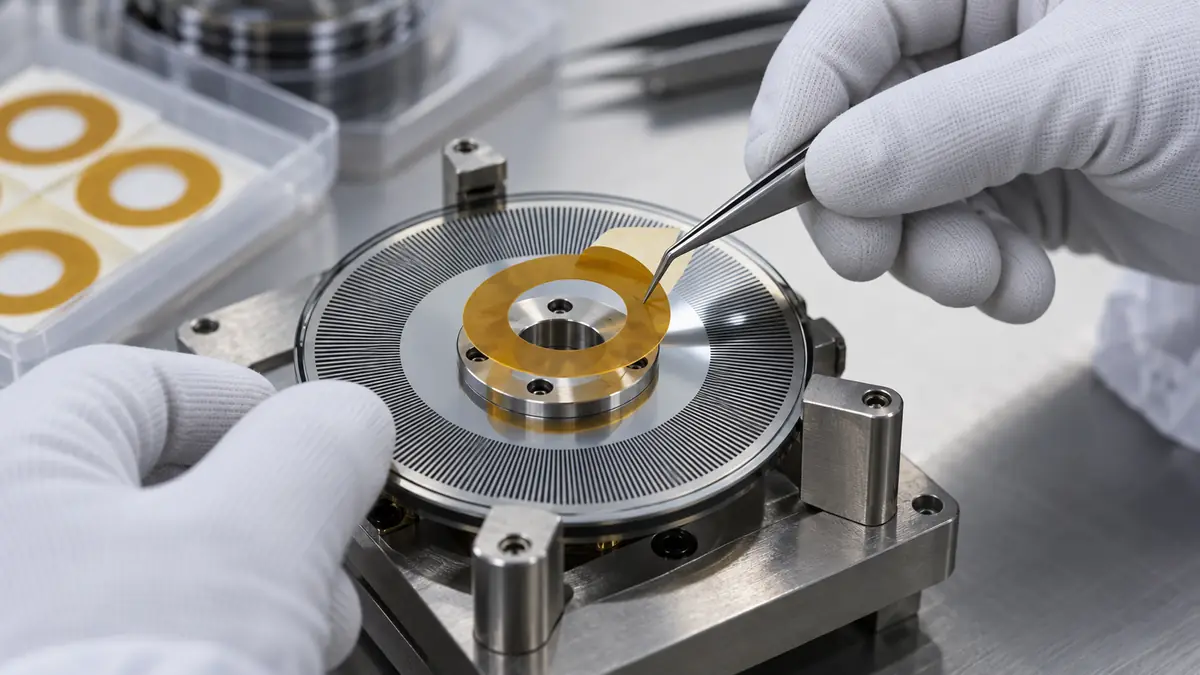
The liner affects whether operators can pick the mask cleanly, distinguish its orientation, and place it without stretching or folding. A split liner, lift edge, extended tab, or carrier can help when the mask is smaller than a gloved fingertip. The die-cut should remain flat and should release without carrying liner fibers or adhesive strings toward the sensor port.
Design for Inspection and Removal
Include a visible edge or pull tab when the assembly allows it. This helps inspectors confirm that the mask is present before processing and completely removed afterward. If a tab is not possible, define a removal tool and a visual standard that will not scratch the housing or push debris into the opening.
Recommended Masking and Validation Workflow
- Confirm the released drawing. Identify the port, keep-out boundary, adhesive land, orientation feature, and acceptable coating edge.
- Inspect the housing. Check burrs, oil, dust, machining residue, dents, and surface changes that can affect sealing.
- Verify the mask lot. Record material, part revision, liner format, shelf condition, and storage history.
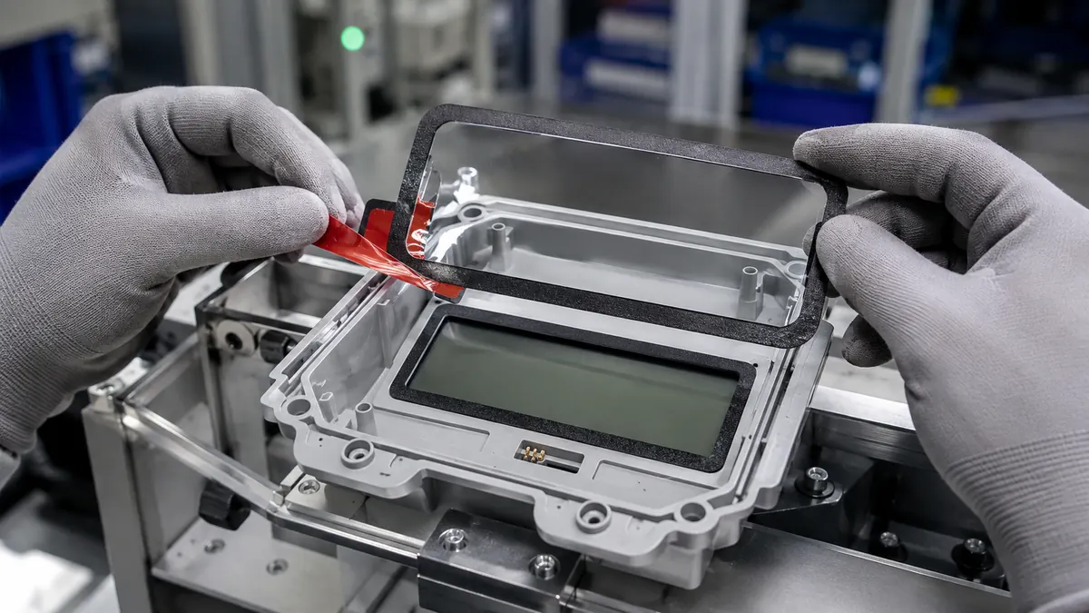
- Remove the mask without touching the adhesive. Use the approved lift edge or applicator and avoid stretching the die-cut.
- Align from a stable datum. Keep the exposed window centered on the functional port and press the adhesive land outward.
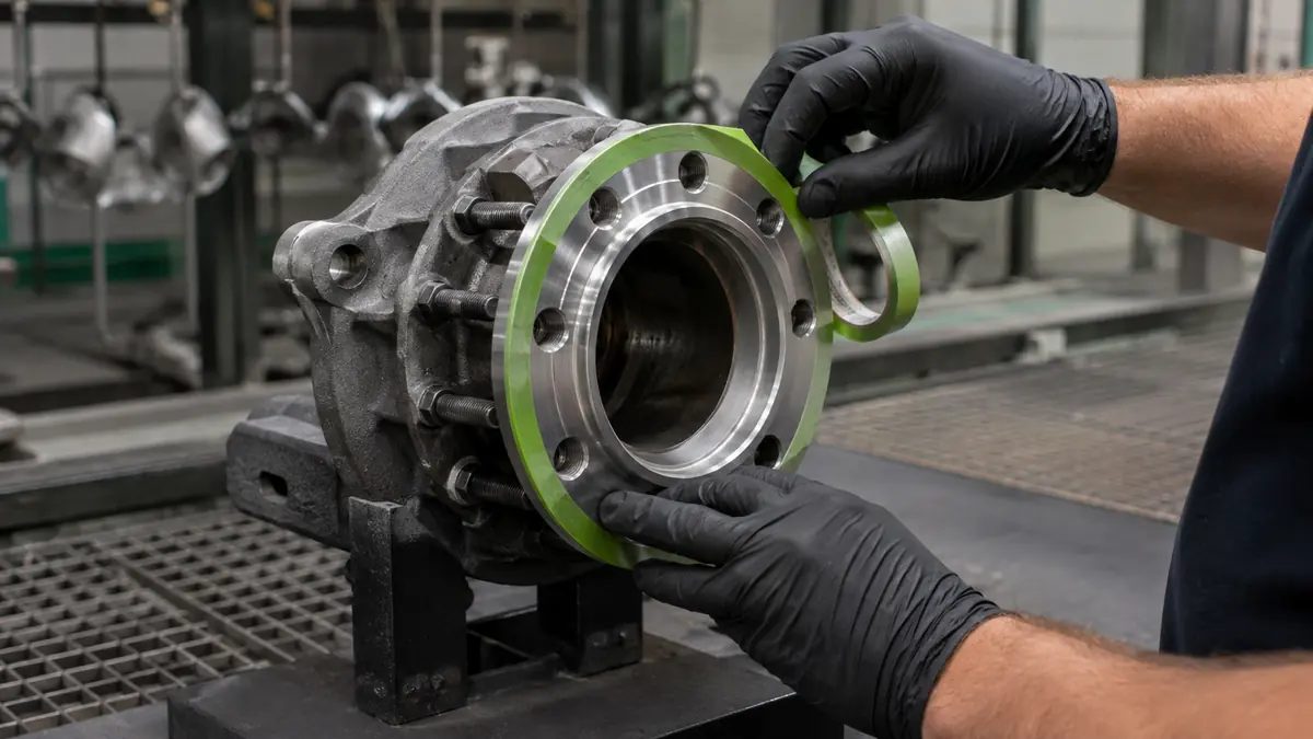
- Burnish the perimeter. Apply controlled pressure around the full edge without forcing the film into the opening.
- Inspect before processing. Confirm presence, orientation, offset, wrinkles, edge lift, and port clearance.
- Run the complete process. Include normal spray direction, cure, transfer, cooling, and waiting time.
- Remove and inspect. Verify the coating boundary, adhesive residue, debris, surface damage, and unobstructed port.
Common Problems and Corrective Directions
| Observed problem | Likely checks | Corrective direction |
|---|---|---|
| Coating reaches the port edge | Mask offset, undersized land, lifted edge, contamination, or spray direction | Revise geometry or placement control and improve edge pressure |
| Mask covers part of the opening | Inside diameter, poor datum, visual parallax, or part variation | Add a keyed feature, larger window, or controlled applicator |
| Adhesive residue remains | Exposure, surface energy, aging, cure, dwell, or removal temperature | Screen another construction and validate the complete cycle |
| Mask is difficult to pick from liner | Liner release, part size, tab design, static, or incomplete die-cutting | Adjust presentation, tab, liner, and converting process |
| Mask is missing after processing | Edge lift, airflow, handling, weak wet-out, or no presence check | Strengthen application inspection and review adhesive contact area |
Related Products and Articles
- Explore custom die-cutting capabilities for films, foams, insulation materials, and masking parts.
- Review what custom die-cut adhesive is and how converted parts are specified.
- See the custom die-cut tape precision assembly guide for format and sourcing principles.
- Share the sensor drawing and process route for a mask-format discussion.
Frequently Asked Questions
Why use a die-cut mask instead of hand-cut tape?
A die-cut can give the port window, outside edge, pull tab, and liner presentation a repeatable geometry. It also removes knife trimming from the sensor assembly area. The benefit must still be confirmed with the actual placement process.
Can one masking tape work for every pressure sensor process?
No. Housing material, surface finish, cleaner, coating, cure, dwell, temperature, and removal condition all affect performance. Qualify the exact tape construction on representative parts.
Should adhesive touch the sensor opening?
The functional port and any diaphragm or capillary path should remain clear unless the sensor designer specifies otherwise. The adhesive should contact only the approved land surrounding the opening.
Can the masks be supplied on a roll for automation?
Yes, many die-cut parts can be presented at a controlled pitch on a liner. Provide the applicator, feed direction, peel plate, part pitch, web width, roll direction, and sensor orientation during development.
What should an RFQ include?
Provide the 2D drawing and 3D geometry, port keep-out zone, housing material and finish, complete process route, temperatures and dwell, allowed offset, removal criteria, presentation format, and annual volume.
Plan a Pressure Sensor Port Masking Trial
Share the sensor drawing, functional opening, adhesive land, coating or potting process, chemistry, cure, surface condition, allowed mask offset, inspection method, and preferred sheet or roll presentation. JIAO TAO TAO can help shortlist a material and die-cut format for controlled qualification.
Contact the technical team about pressure sensor port masks.
PET Silicone Tape for Composite Panel Cure Masking
PET Silicone Tape for Electroplating Rack Contact Masking
Related Article

Need help choosing the right industrial tape?
Send us your application details, including temperature, surface material, size, quantity and current problem. Our team will help recommend a suitable tape material or custom die-cut solution.

simon@jiaotaotao.com


+86-136 1277 5969


+86-136 1277 5969
