
Custom Die-Cut Tape for Automotive Mirror Heater Pad Bonding
Custom Die-Cut Tape for Automotive Mirror Heater Pad Bonding
Custom die-cut tape for automotive mirror heater pad bonding can simplify alignment, keep adhesive away from terminals, and create a repeatable bond line between a heater element and the rear surface of side-mirror glass. The die-cut must be engineered around the actual mirror geometry, heater construction, substrate coatings, environmental exposure, and assembly sequence. It should be approved through representative production trials rather than selected from adhesive name alone.

Key Takeaways
- Design the adhesive shape from released mirror and heater drawings, including terminals, sensor zones, edges, and datums.
- Match the carrier and adhesive to glass coatings, heater-film surface energy, heat cycles, moisture, vibration, and service life.
- Use a split or extended liner when the operator needs staged placement and a reliable peel tab.
- Control pressure, dwell, temperature, and time before functional testing.
- Approve the complete converted part and process with representative assemblies.
What Mirror Heater Pad Bonding Must Control
The adhesive layer has several jobs. It holds the heater pad flat against the mirror back, transfers assembly pressure without wrinkling the flexible circuit, and avoids interference with terminals or local features. A shape that is too narrow may reduce bonded area, while an oversized shape can create squeeze-out, contaminate contact zones, or become visible at the mirror edge.
Mirror backs are not all equivalent. They may include reflective coatings, protective paints, conductive layers, markings, bus bars, clips, or local curvature. The heater side may be polyester film, printed conductive ink, coated foil, or another construction. Adhesion testing must use the real surfaces and the approved cleaning method.
Die-Cut Constructions to Compare
| Construction | Potential fit | Main qualification point |
|---|---|---|
| Thin film-carrier double-sided tape | Stable, precise shapes and controlled thickness | Conformity to curvature and long-term edge stress |
| Tissue-carrier double-sided tape | General lamination where some hand conformability helps | Moisture resistance, tear behavior, and placement control |
| Foam carrier | Gap filling or stress distribution on uneven assemblies | Thickness tolerance, compression set, and edge visibility |
| Unsupported transfer adhesive | Very thin bond lines and complex contours | Handling, stretching, liner release, and application tooling |
Information Required Before Die-Cut Design
| Input | What to define | Why it matters |
|---|---|---|
| Geometry | Mirror outline, heater outline, holes, terminals, keep-outs, datum scheme, and tolerance | Determines the adhesive path and converted-part accuracy |
| Surfaces | Glass-back coating and heater-film material, texture, contamination risk, and surface energy | Controls adhesive wet-out and durability |
| Environment | Temperature cycles, condensation, humidity, cleaning chemicals, vibration, and storage | Defines the exposure sequence for qualification |
| Assembly | Manual or automated placement, pressure tool, dwell, takt time, and rework policy | Influences liner design and handling stiffness |
| Acceptance | Position tolerance, edge lift, bubbles, peel behavior, heater function, and appearance | Turns the trial into a measurable decision |
Choose a Carrier for Geometry and Handling
A dimensionally stable film carrier can support precise outlines and clean apertures. Tissue can be easier to laminate manually but may be less stable around narrow bridges. Foam can absorb unevenness but changes the stack height. Transfer adhesive creates a thin bond line, yet it often needs a well-designed liner and application fixture to prevent stretching.
Design Keep-Outs Around Electrical Features
Terminals, bus bars, sensors, printed traces, and connector relief zones should be shown on the drawing. Add practical clearance for placement variation without sacrificing needed bonded area. Rounded internal corners can reduce tear initiation in narrow adhesive webs, while registration holes or asymmetrical features can prevent reversed installation.
Engineer the Release Liner
The liner is part of the assembly tool. An extended tab helps operators start removal without touching the adhesive. A split liner can expose one controlled section for initial registration, then release the remaining area during lamination. Liner stiffness, split direction, release level, and static behavior should be tested on the actual station.
Recommended Assembly Workflow
- Verify incoming parts. Confirm mirror coating, heater revision, die-cut revision, liner orientation, and storage condition.
- Prepare the surfaces. Use only the approved cleaner and lint-control method, then allow the surfaces to reach the specified dry condition.
- Load the fixture. Support the mirror without point stress and align the heater or adhesive from stable datums.
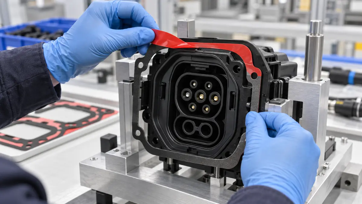
- Expose the first adhesive zone. Use the liner tab without touching or stretching the die-cut.
- Register and laminate. Apply progressively with the qualified roller, pad, or press rather than trapping air from both sides.
- Apply controlled pressure. Keep force, contact area, duration, and temperature within the approved work instruction.
- Allow dwell before test. Do not treat immediate handling strength as final bond performance.
- Inspect and record. Check alignment, edge contact, bubbles, terminal clearance, heater function, and traceability.
Failure Modes and Corrective Directions
| Observed issue | Checks | Corrective direction |
|---|---|---|
| Edge lift after cycling | Surface compatibility, curvature, adhesive stress, contamination, and bond-line width | Reassess construction, preparation, geometry, and pressure |
| Heater pad shifts during lamination | Datum control, liner split, fixture clearance, and application direction | Use staged exposure or improve registration features |
| Bubbles or wrinkles | Lamination direction, roller profile, part flatness, and operator access | Apply progressively and support the flexible pad |
| Adhesive enters a terminal zone | Die-cut tolerance, keep-out size, squeeze-out, and placement variation | Revise the aperture and tighten the datum strategy |
| Die-cut stretches during placement | Unsupported adhesive, liner release, narrow bridges, and peel angle | Add a carrier or redesign the handling liner |
Qualification Plan
Build the test matrix from the actual risks. Include representative coating lots, heater lots, minimum and maximum geometry conditions, approved cleaning, realistic assembly delay, and environmental sequences relevant to the finished mirror. Inspect alignment and bond condition before and after exposure, then confirm electrical function without claiming that the adhesive itself provides electrical performance.
For a supplier request, provide drawings with controlled dimensions and keep-outs, substrate descriptions, expected exposures, assembly method, liner preference, annual and batch quantities, packaging orientation, and acceptance criteria. Do not send only a photograph when a tolerance-controlled shape is required.
Related Products and Articles
- Review custom die-cutting capabilities for liner, tab, kiss-cut, and packaging options.
- Compare carrier families in the industrial double-sided tape range.
- See the control-panel bonding guide for another precision lamination workflow.
- Send the mirror and heater drawings for a converted-part discussion.
Frequently Asked Questions
Why use a custom die-cut instead of hand-applied strips?
A die-cut can follow the mirror outline, preserve terminal keep-outs, add liner tabs, and support repeatable placement. Hand-applied strips may suit prototypes but create more seams and operator-dependent geometry.
Which double-sided tape carrier is best for a mirror heater?
There is no universal carrier. Film, tissue, foam, and transfer adhesive offer different handling, thickness, conformity, and durability. The correct choice depends on the real surfaces, geometry, exposures, and assembly process.
Can the adhesive cover printed heater traces?
Only if the heater designer permits it and the exact construction is qualified. Terminals, sensors, bus bars, and other defined keep-outs should be protected by the die-cut geometry.
What liner features help manual assembly?
Extended pull tabs, split liners, asymmetrical orientation, and stable release can support staged placement. The best direction depends on the station layout and lamination path.
What should be included in an RFQ?
Include controlled drawings, surface materials, environmental sequence, assembly method, adhesive and thickness constraints, liner design, tolerances, packaging orientation, quantities, and acceptance tests.
Plan a Mirror Heater Bonding Trial
Share the mirror and heater drawings, coating descriptions, environmental sequence, assembly pressure method, terminal keep-outs, liner preference, and inspection criteria. JIAO TAO TAO can help shortlist a double-sided construction and die-cut format for controlled evaluation.
PET Silicone Tape for Bearing Bore Masking During Powder Coating
PET Silicone Tape for Composite Panel Cure Masking
Related Article

Need help choosing the right industrial tape?
Send us your application details, including temperature, surface material, size, quantity and current problem. Our team will help recommend a suitable tape material or custom die-cut solution.

simon@jiaotaotao.com


+86-136 1277 5969


+86-136 1277 5969
