
PET Silicone Tape for Bearing Bore Masking During Powder Coating
PET Silicone Tape for Bearing Bore Masking During Powder Coating
PET silicone tape for bearing bore masking during powder coating helps keep precision fits, seal lands, and selected machined faces free from overspray and cured powder. The job is more demanding than covering a flat panel: the mask must follow a circular edge, stay seated through handling and oven exposure, and remove without damaging the specified finish. A successful specification therefore combines tape construction, mask geometry, surface preparation, removal timing, and a representative line trial.

Key Takeaways
- Define exactly which diameter, shoulder, chamfer, and adjacent face must remain coating-free.
- Choose the PET film, silicone adhesive, thickness, and width as one qualified construction.
- Use die-cut rings when repeatability matters more than the flexibility of hand-applied strips.
- Keep tape out of the fit surface and avoid wrinkles that can create powder bridges.
- Validate edge quality, removal, residue, and dimensional cleanliness on the real coating line.
Why Bearing Bores Need a Controlled Mask
A bearing bore is normally produced to a defined diameter, roundness, and surface condition. Powder on the fit surface can interfere with assembly, while an unnecessarily large no-coat area can reduce corrosion protection or change the intended appearance. The drawing should identify the protected bore, any seal land or counterbore, the permissible mask edge, and whether the chamfer is coated or bare.
Masking also has to survive part loading, grounding, spray, oven movement, cooling, and unmasking. PET film provides a thin, dimensionally stable mask face, while a suitable silicone pressure-sensitive adhesive can help the mask remain seated during elevated-temperature processing. Those general material traits do not establish fitness for a specific cure schedule; buyers should qualify the exact product and line conditions.
Mask Formats to Compare
| Format | Best-fit situation | Control point |
|---|---|---|
| Narrow PET tape strip | Low volume, changing diameters, or development trials | Operator overlap and circular edge consistency |
| Die-cut PET ring | Repeated bore sizes and visible mask boundaries | Outside/inside diameter, liner design, and placement tolerance |
| Plug plus face ring | Bore depth and surrounding face both need protection | Interface between plug and tape; avoid exposed gaps |
| Reusable cap or plug | Robust geometry and high repeat volume | Fit, cleaning, distortion, and line maintenance |
| Machining after coating | Drawing and process plan permit finish removal | Added operation, chips, fixturing, and corrosion strategy |
PET Silicone Tape Selection Inputs
| Input | What to record | Why it matters |
|---|---|---|
| Coating cycle | Preheat, cure temperature profile, dwell, cooling, and repeat exposure | Heat history affects film, adhesive, and removal |
| Part surface | Alloy, pretreatment, roughness, oil, cleaner, and dryness | Adhesion changes with surface energy and contamination |
| Geometry | Bore diameter, shoulder, chamfer, depth, nearby ribs, and mask tolerance | Geometry determines width or die-cut design |
| Powder process | Gun direction, electrostatic settings, grounding method, reclaim, and film build target | Powder can wrap around edges or bridge seams |
| Removal | Removal temperature, direction, access, residue limit, and disposal method | Unmasking is part of the qualified process |
Film and Adhesive Construction
Specify the complete construction rather than asking only for “green high-temperature tape.” Compare PET backing thickness, total thickness, silicone adhesive coat, release behavior, and dimensional stability. A thicker tape can be easier to handle but may create a higher powder edge. A thinner tape can conform well but may be harder to position without stretching or folding.
Width, Ring Geometry, and Liner
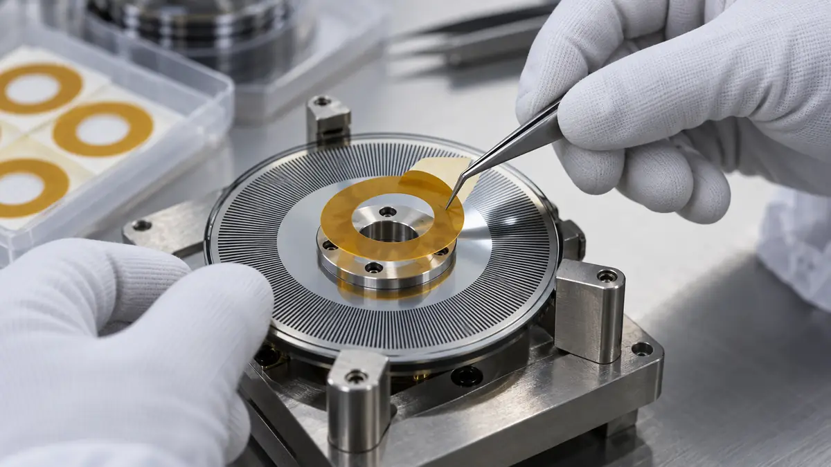
For hand masking, the width should cover the required no-coat band without extending onto critical assembly surfaces. For die-cut rings, define inner and outer diameters, any split or pull tab, the carrier liner, and orientation features. A split liner can support accurate placement without touching the adhesive, while a pull tab can reduce damage during unmasking.
Edge Quality Versus Removal
High adhesion is not automatically better. The mask must resist lifting during the process but still remove within the approved window. Evaluate powder bridging, adhesive transfer, film tearing, edge staining, and any effect on pretreatment or adjacent coating. The best balance depends on the actual part and line.
Application and Removal Workflow
- Confirm the drawing. Identify every protected surface and the allowed mask-edge tolerance before parts reach the line.
- Inspect the bore. Reject burrs, chips, heavy oil, trapped liquid, or damage that could cut the tape or compromise the fit.
- Prepare the surface. Use the approved plant cleaning and pretreatment sequence; allow the mask area to be clean and dry.
- Apply without touching the adhesive. Center the strip or die-cut ring, then press it from the bore edge outward to remove air pockets and wrinkles.
- Check the perimeter. Inspect the full circular edge, overlap, tab position, and clearance from grounding or hanging points.
- Run the qualified coating cycle. Do not infer suitability from a catalog maximum; reproduce the real thermal and handling profile.
- Remove in the defined window. Peel at the validated angle and part temperature without dragging loose powder across the bore.
- Inspect and record. Verify the no-coat boundary, bore cleanliness, residue, coating damage, and lot traceability.
Common Defects and Corrective Direction
| Observed defect | Likely checks | Corrective direction |
|---|---|---|
| Powder inside the bore | Edge lift, seam gap, wrinkling, narrow coverage, or spray direction | Improve perimeter contact or change mask geometry |
| Jagged coating edge | Stretched tape, poor centering, rough surface, or powder bridge | Use a die-cut ring or revise application pressure |
| Adhesive residue | Wrong construction, extended heat, contamination, or late removal | Requalify adhesive and removal window |
| Tape tears on removal | Thin backing, sharp burr, powder lock, or awkward pull angle | Remove the damage source and consider a tabbed format |
| Coating chips beside the mask | Excess film build, bridge formation, cold removal, or steep peel | Review coating edge and validated peel method |
Qualification Plan for Production
Test the smallest and largest bore variants, worst-case surface condition, longest approved cure profile, and realistic delay before removal. Include parts from different rack positions because airflow and heating may vary. Measure what the drawing requires after masking and coating; do not rely only on a visual check when the bearing fit is dimensionally controlled.
Acceptance criteria can cover mask position, clean bore surface, coating-edge continuity, absence of residue, removal time, and assembly fit. A material, supplier, thickness, liner, cleaning, or cure change should trigger documented review before full production use.
Related Products and Articles
- Explore PET polyester silicone tape options.
- Review the high-temperature masking tape guide.
- Compare a higher-heat film family on the polyimide tape page.
- Send a bore drawing and coating cycle for a construction discussion.
Frequently Asked Questions
Can PET silicone tape protect the complete depth of a bearing bore?
A face ring mainly controls the entry and surrounding land. If the complete depth must remain coating-free, the process may need a qualified plug, a combined plug-and-ring mask, or another engineered method.
Should the bore chamfer be masked?
The part drawing should decide. Some assemblies require the chamfer bare; others allow coating up to a defined edge. Do not let the tape operator choose this boundary informally.
Is a die-cut ring better than a hand-applied strip?
A die-cut ring can improve repeatability and speed for stable high-volume geometry. Hand-applied tape remains useful for prototypes, repair, and multiple low-volume sizes when operator controls are adequate.
When should the tape be removed?
Use a removal window established by the coating trial and workplace safety procedure. Part temperature, powder state, adhesive construction, access, and edge-chipping risk all affect the best timing.
What information belongs in an RFQ?
Provide the bore drawing, protected surfaces, substrate and pretreatment, cure profile, powder system, mask quantity, manual or automated placement method, liner preference, removal condition, and acceptance criteria.
Plan a Bearing Bore Masking Trial
Share the bore dimensions, no-coat boundary, pretreatment, powder cycle, handling sequence, and inspection method. JIAO TAO TAO can help shortlist PET silicone tape or a die-cut ring format for controlled evaluation.
Custom Die-Cut Tape for Automotive Shark-Fin Antenna Bonding
Custom Die-Cut Tape for Automotive Mirror Heater Pad Bonding
Related Article

Need help choosing the right industrial tape?
Send us your application details, including temperature, surface material, size, quantity and current problem. Our team will help recommend a suitable tape material or custom die-cut solution.

simon@jiaotaotao.com


+86-136 1277 5969


+86-136 1277 5969
